Dry test strip with controlled flow and method of manufacturing same

Active Publication Date: 2008-05-15
POLYMER TECH SYST
View PDF41 Cites 142 Cited by
  • Summary
  • Abstract
  • Description
  • Claims
  • Application Information

AI Technical Summary

Benefits of technology

[0009]The present invention provides a solution to the above problems by providing a dry test strip carrier system in which the compression the carrier applies to a strip is accurately controlled. The accurate control of the compression permits more accurate control of the flow of the fluid through the strip and, thus, improves the repeatability and accuracy of the test. The compression is controlled with parameters to provide consistent flow from one test strip to another. The accur

Problems solved by technology

If the strip is held loosely in the carrier, flow is augmented, but the strip can move, which can lead to erroneous results.
If the strip is held firmly, damage can result, which leads to erratic results as well as inaccuracies.
However, the accuracies of test strips st

Method used


Image

  • Dry test strip with controlled flow and method of manufacturing same
  • Dry test strip with controlled flow and method of manufacturing same
  • Dry test strip with controlled flow and method of manufacturing same

Examples


Example

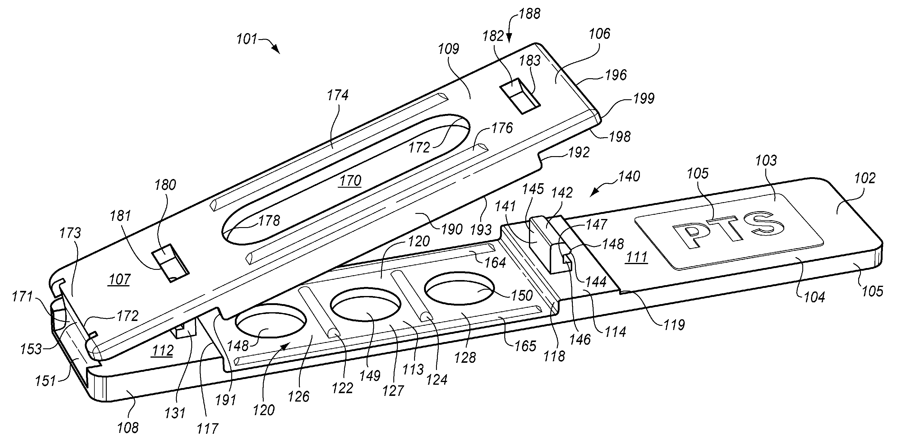
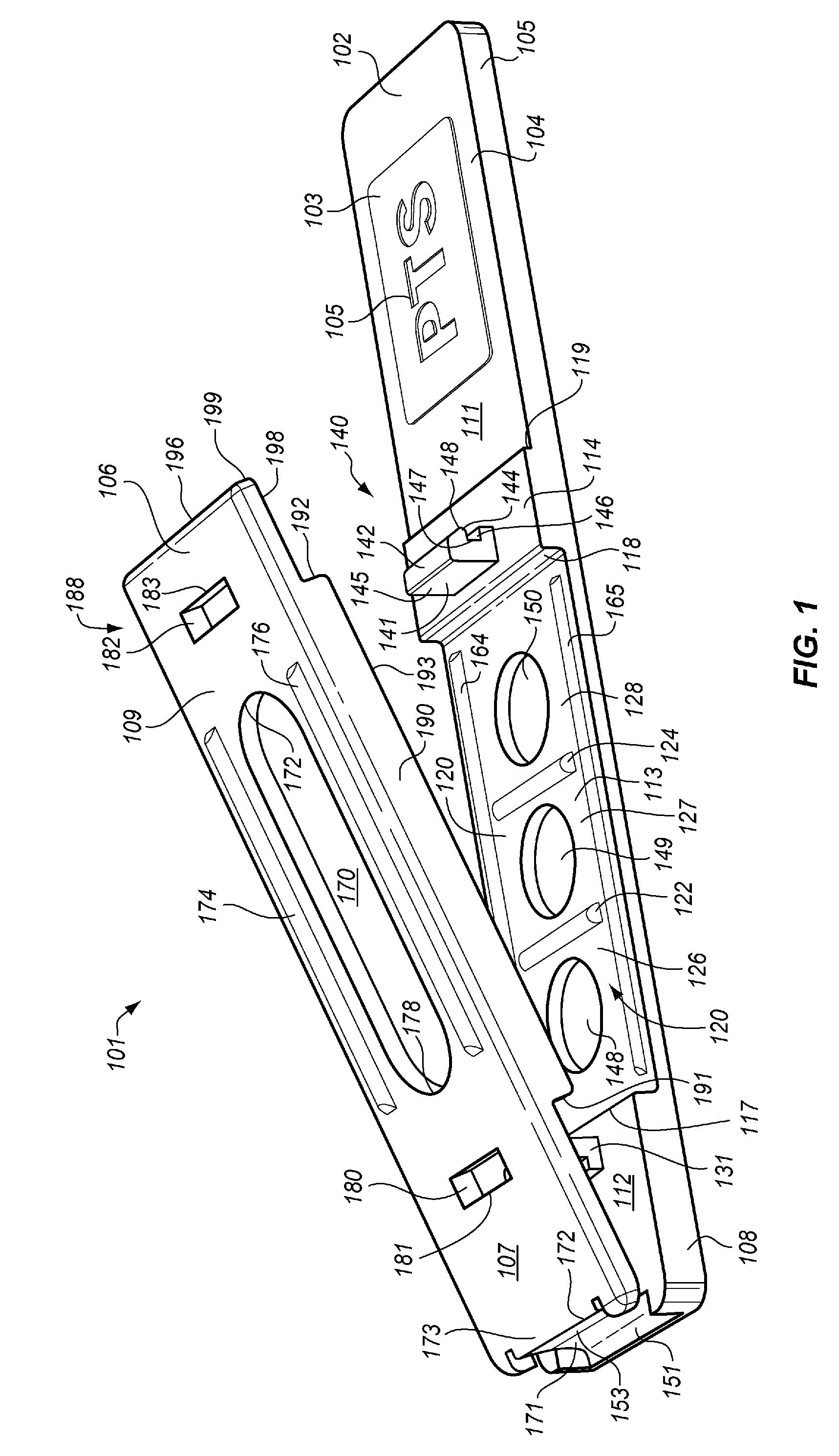
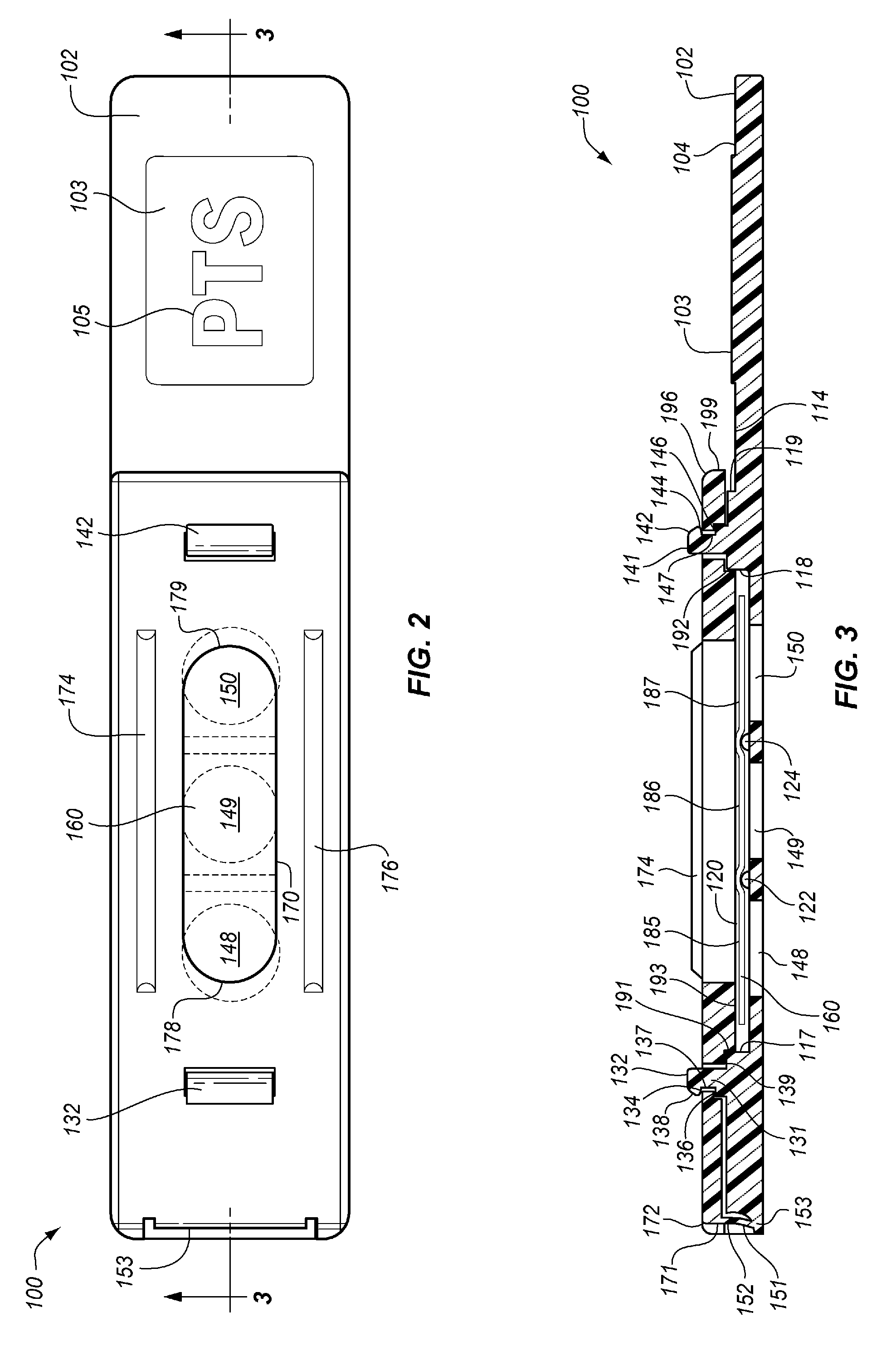
[0041]For the purposes of promoting an understanding of the principles of the invention, reference will now be made to the embodiments illustrated in the drawings and described in the following written specification. It is understood that no limitation to the scope of the invention is intended thereby. It is further understood that the present invention includes any alterations and modifications to the illustrated embodiments and includes further applications of the principles of the invention as would normally occur to one skilled in the art to which this invention pertains. It should also be understood that, in accordance with the patent law, the drawings are not intended to be precise engineering drawings of the invention, but rather are only intended to illustrate the invention. For example, the scale of the drawings and relative size of the various parts are generally altered so as to better illustrate the invention within the constraints of a written document such as this.

[004...


PUM

PropertyMeasurementUnit
Fractionaaaaaaaaaa
Heightaaaaaaaaaa
Heightaaaaaaaaaa

Abstract

A dry test strip assembly includes: a carrier base having a test port and a well adapted for receiving a dry test strip element, and a cover having a sample opening. The cover can be snapped onto the base with the sample opening aligned over the test port and with a test strip element compressed between the base and cover. A maximum dry test strip compression stop controls the maximum compression on the dry test strip, and a minimum dry test strip compression stop controls the minimum compression on the dry test strip. A rib between two test ports prevents fluid flow in the dry test strip element from one side of the rib to another, thereby separating the test strip element into a plurality of separate fluid compartments. A manufacturing system efficiently assembles the dry test strip assembly without handling by humans.

Description

CROSS-REFERENCE TO RELATED APPLICATIONS[0001]This application is a continuation-in-part of U.S. patent application Ser. No. 11 / 207,121 filed Aug. 17, 2005, which itself is a continuation-in-part of U.S. patent application Ser. No. 10 / 962,272 filed Oct. 11, 2004, which claims the benefit of U.S. Provisional Application No. 60 / 541,681 filed Feb. 3, 2004. U.S. patent application Ser. No. 11 / 207,121 also claims the benefit of U.S. Provisional Application No. 60 / 602,210 filed Aug. 17, 2004. All of the above patent applications, both provisional and non-provisional, are hereby incorporated by reference to the same extent as though fully contained herein.FIELD OF THE INVENTION[0002]The invention in general relates to bodily fluid analysis systems including a disposable test strip, with particular application to on-site testing of particular analytes in blood.BACKGROUND OF THE INVENTION[0003]The level of certain analytes in blood and other body fluids is often used to diagnose disease, dete...

Claims


Application Information

Patent Timeline
IPC IPC(8): B01J19/00B23P11/00
CPCG01N21/78G01N21/8483G01N33/52G01N33/526Y10T29/49826G01N2021/8494G01N2021/8654G01N2201/0221G01N2800/044G01N33/92
Inventor HUFFSTODT, ROBERTHANCOCK, JOHN P.CRABTREE, EMMANUEL P.SUTOR, JAMES J.HUFFSTODT, KIMBERLY ZINSERLAWRENCE, GREGORY M.
Owner POLYMER TECH SYST
Why Eureka
Try Eureka