Separator assembly

Active Publication Date: 2008-05-22
PARKER HANNIFIN LTD HEMEL HEMPSTEAD
View PDF24 Cites 18 Cited by
  • Summary
  • Abstract
  • Description
  • Claims
  • Application Information

AI Technical Summary

Benefits of technology

[0003]Removal of material from a gas stream can be required to ensure that the gas is sufficiently clean for a subsequent application, or to minimise adverse effects of impurities on components of the system. For example, removal of compressor oil can be required to minimise chemical contamination

Problems solved by technology

Typically, the higher the pressure drop across a separator assembly in a compressed gas syst

Method used


Image

  • Separator assembly
  • Separator assembly
  • Separator assembly

Examples


Embodiment Construction

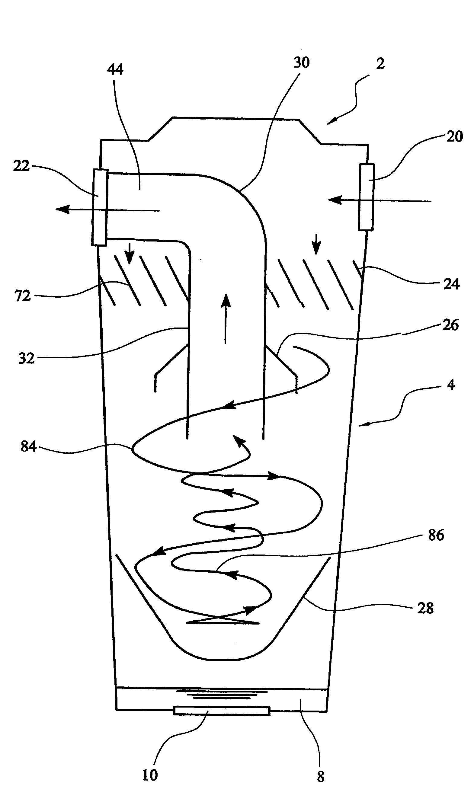
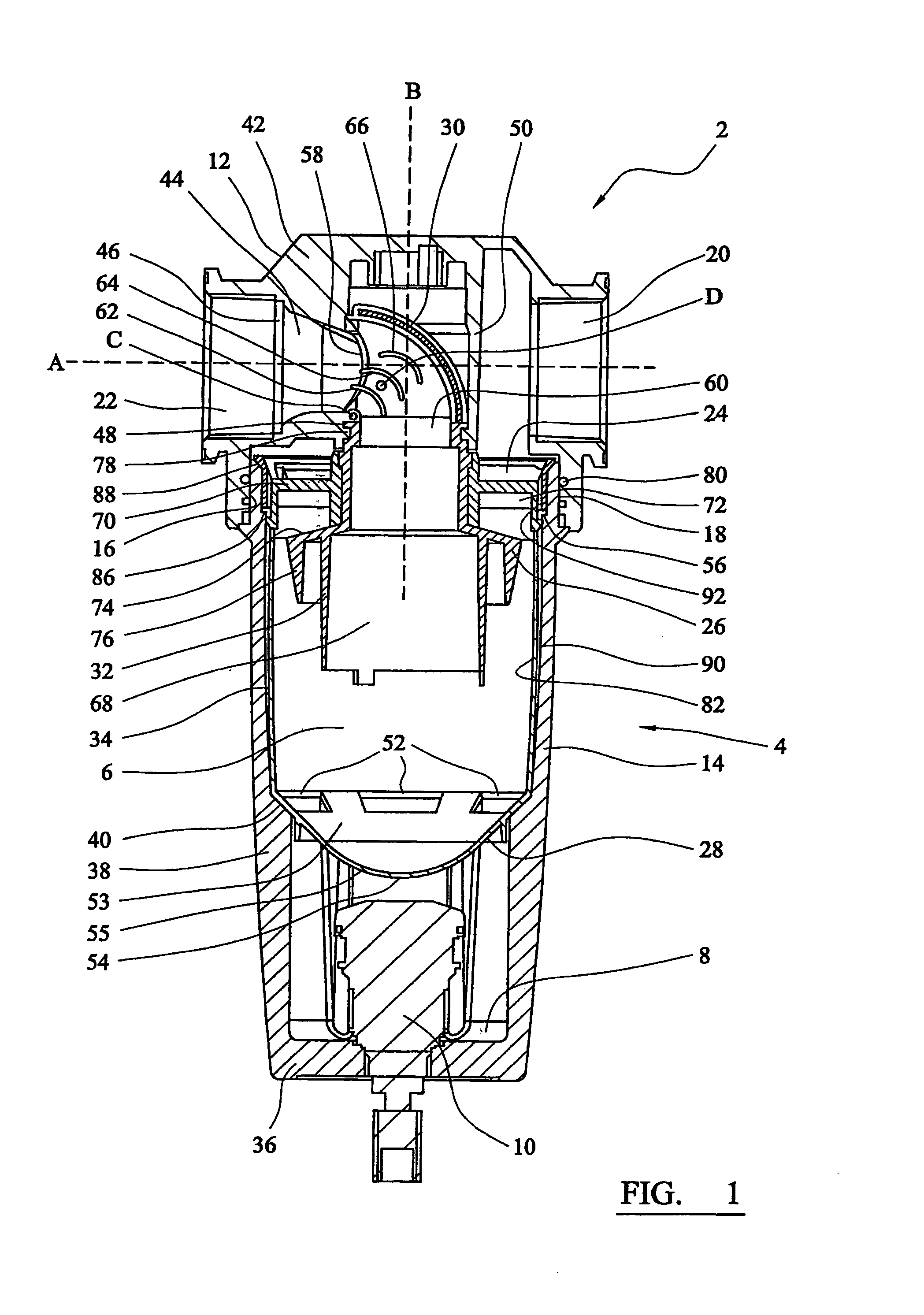
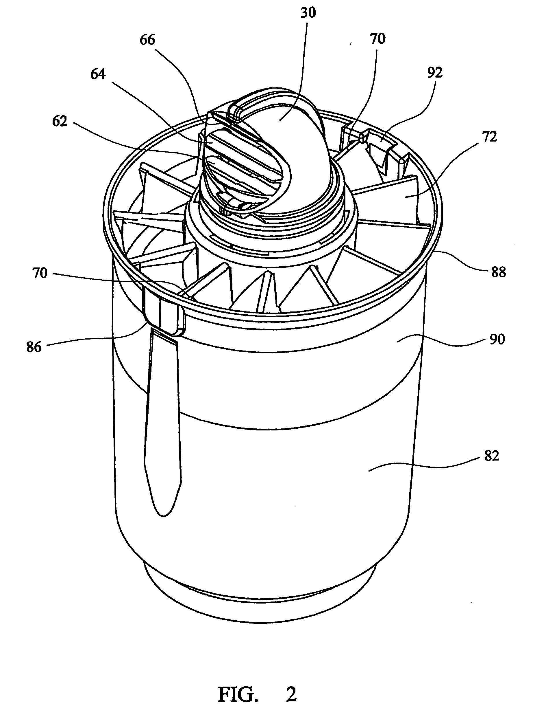
[0061]Referring to the drawings, FIG. 1 shows a separator assembly 2, which comprises a housing 4 defining an inner volume 6. The housing 4 comprises a head part 12, and a body part 14 which can be connected to one another by means of cooperating screw threads at their interfaces 16, 18. The housing 4 further comprises inlet 20 and outlet 22 ports located in the head part 12, for gas to enter and exit the separator assembly 2, a reservoir 8 located at a second end of the housing opposite the first end, and a liquid drainage port 10. The separator assembly further comprises a flow director 24, a flow deflector 26, a shield 28, a flow conduit device 30 which includes a conduit portion 32, all located within the body part 14 of the housing 4.

[0062]The head part 12 and body part 14 are formed from a metallic material, especially aluminium or an alloy thereof. They can be formed by machining or by techniques such as casting.

[0063]The body part 14 comprises a cylindrical wall 34, an end w...


PUM

PropertyMeasurementUnit
Forceaaaaaaaaaa
Flow rateaaaaaaaaaa
Diameteraaaaaaaaaa

Abstract

A separator assembly for removing material that is entrained in a gas stream. The separator assembly comprises a housing having inlet and outlet ports for the gas from which material is to be removed. The inlet and outlet ports are located toward the upper end of the housing. A flow director is positioned so that gas flowing into the housing flows over the flow director so that the incoming gas is made to follow a generally helical path within the housing. The separator assembly also comprises a shield which extends across the housing towards the lower end thereof so as to leave a collection space between it and the lower end in which material that is separated from the gas stream can collect. There is at least one opening in or around the shield through which the material can flow past the shield into the collection space. The face of the shield which is directed towards the upper end of the housing is bowl-shaped.

Description

CROSS REFERENCE TO RELATED APPLICATIONS[0001]This application is continuation of copending International Application No. PCT / GB06 / 002737 filed Jul. 21, 2006, which designated the United States, the disclosure of which is incorporated herein by reference, and which claims priority to Great Britain Patent Application Nos. 05241173.2, filed Nov. 28, 2005; and 0515264.0, filed. Jul. 26,2005.BACKGROUND OF THE INVENTION[0002]The present invention relates to a separator assembly for removing material that is entrained in a gas stream such as liquid in an aerosol form.SUMMARY OF THE INVENTION[0003]Removal of material from a gas stream can be required to ensure that the gas is sufficiently clean for a subsequent application, or to minimise adverse effects of impurities on components of the system. For example, removal of compressor oil can be required to minimise chemical contamination and accumulation on valves which might lead to malfunction of the valves, and removal of particulate solid ...

Claims


Application Information

Patent Timeline
IPC IPC(8): B01D45/00
CPCB01D45/06B01D45/16B04C5/181B04C5/103B04C5/13B04C5/06Y10S55/17
Inventor LANE, BRIANBITTLE, STEPHENTROWSDALE, RAY
Owner PARKER HANNIFIN LTD HEMEL HEMPSTEAD
Why Eureka
Try Eureka