Grate apparatus and method

a technology of grate and grate plate, which is applied in the direction of lighting and heating equipment, household stoves or ranges, heating types, etc., can solve the problems of grate coated with any of a number of known non-stick coatings, prone to discoloration and staining, and cannot withstand the severe abrasion of non-stick coatings

Inactive Publication Date: 2008-05-22
GENERAL ELECTRIC CO
View PDF10 Cites 5 Cited by
  • Summary
  • Abstract
  • Description
  • Claims
  • Application Information

AI Technical Summary

Benefits of technology

[0005]As described herein, embodiments of the invention overcome one or more of the above or other disadvantages known in the art.

Problems solved by technology

However, the porcelain enamel coating is susceptible to discoloration and staining, especially when subjected to high temperatures from the heat source.
However, a grate coated with any of a number of known non-stick coatings also suffers from numerous disadvantages.
These non-stick coatings cannot withstand the severe abrasion resulting from movement of the cooking utensil on the grate.
Further, the non-stick coatings do not provide enough friction between the cooking utensil and the grate, resulting in instability of the cooking utensil on the grate.

Method used


Image

  • Grate apparatus and method
  • Grate apparatus and method
  • Grate apparatus and method

Examples


Embodiment Construction

[0012]Embodiments of the invention are described below, with reference to the figures. Throughout the figures, like reference numbers indicate the same or similar components.

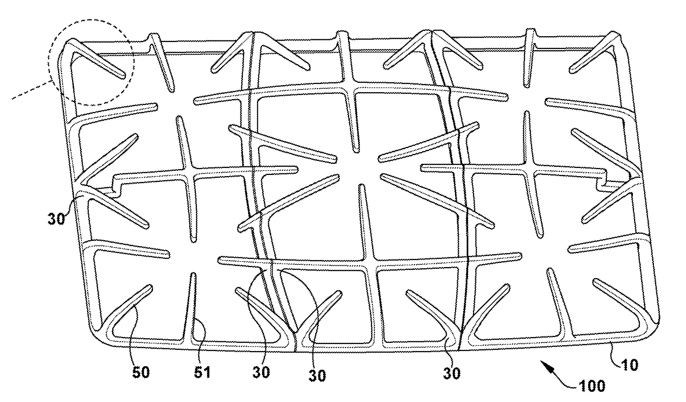
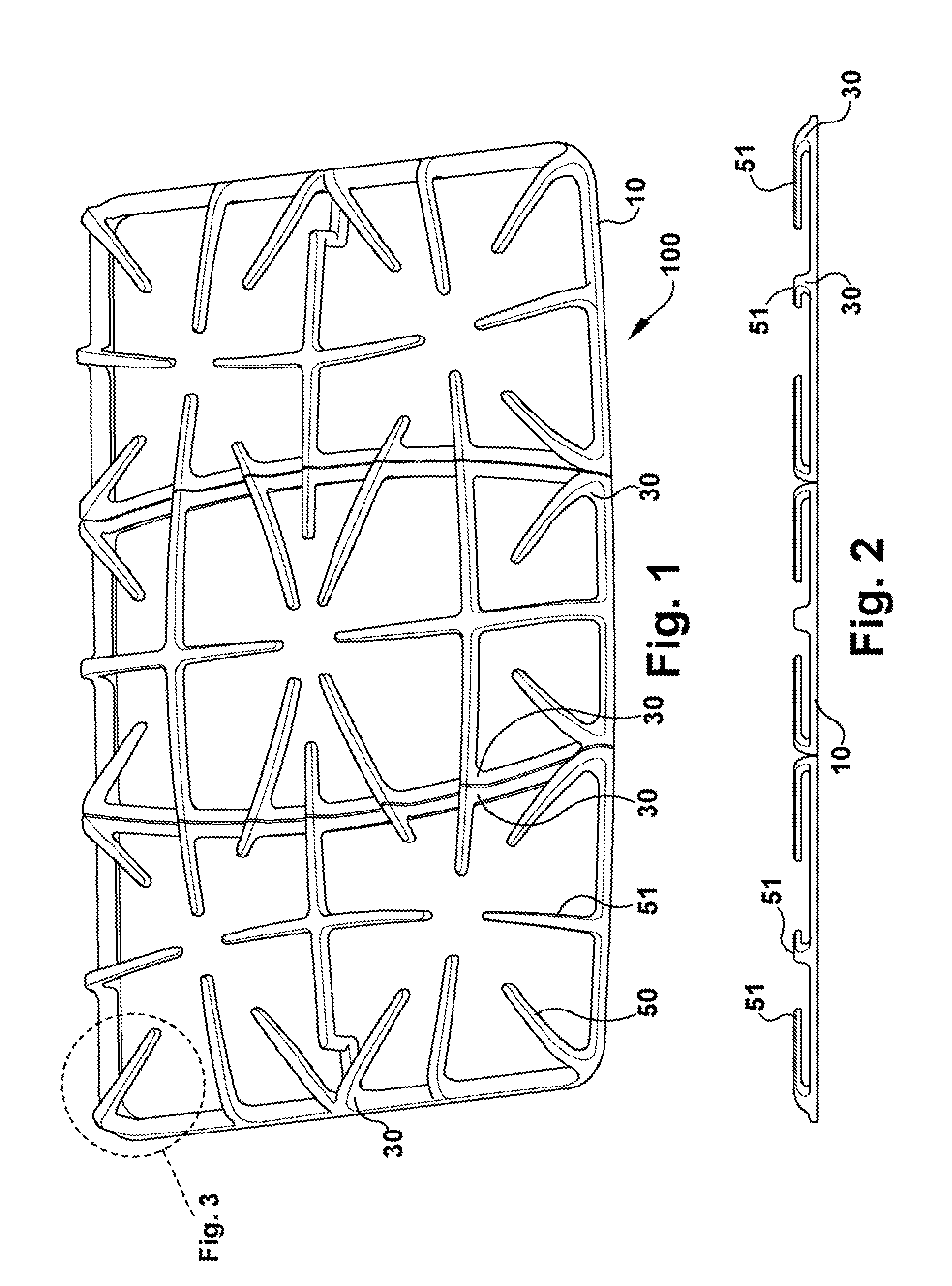
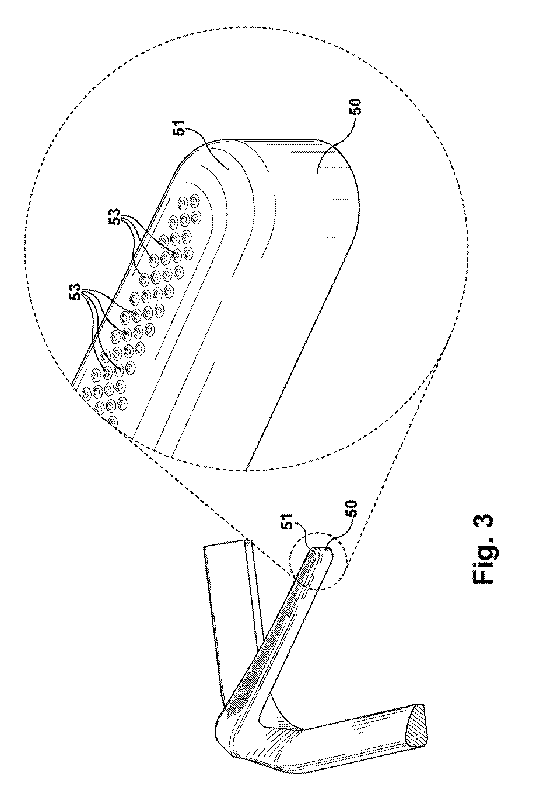
[0013]FIG. 1 is a top isometric view of an embodiment of a grate apparatus. FIG. 2 is a side view of the grate apparatus, and FIG. 3 is a detail view of a portion of the grate apparatus. As shown in the drawings, the grate apparatus 100 includes a base portion 10. The base portion 10 is configured to support the grate apparatus 100 on a range stove (such as a range cook top), whether the range stove is separate from or part of an oven, and whether the range stove has one or more heat sources (e.g., burners). Although the drawings show specific embodiments of the base portion 10, the base portion 10 can include additional or different components, as long as the base portion 10 can support the grate apparatus 100 on the range stove.

[0014]The grate apparatus 100 also includes a plurality of each of utensil supporti...


PUM

PropertyMeasurementUnit
heightaaaaaaaaaa
heightaaaaaaaaaa
temperaturesaaaaaaaaaa

Abstract

A grate apparatus configured to support a cooking utensil on a range stove. The grate apparatus includes a base portion configured to be disposed on the range stove. An intermediate portion extends from the base portion. A utensil supporting portion is connected to the base portion through the intermediate portion. The supporting portion includes a top surface configured to face and be disposed opposite the cooking utensil. The top surface includes a plurality of protrusions configured to support the cooking utensil.

Description

BACKGROUND OF THE INVENTION[0001]The described technology relates to a grate apparatus, such as for a range stove or oven, and a corresponding method.[0002]It is known to use a grate on a range, such that a cooking utensil is spaced apart form a heat source used to heat the cooking utensil. Such a heat source includes a frame produced by the combustion of natural gas or propane.[0003]It is also known to form the grate from cast iron, and to coat the grate with porcelain enamel. The coated grate is easier to clean and has a more attractive appearance as compared to an uncoated grate. However, the porcelain enamel coating is susceptible to discoloration and staining, especially when subjected to high temperatures from the heat source. Thus, the aesthetic quality of the porcelain enamel coated grate is negated.[0004]Therefore, it may be desirable to coat the grate with a material resistant to discoloration and staining, such as a non-stick coating. However, a grate coated with any of a...

Claims


Application Information

Patent Timeline
Patent Type & Authority Applications(United States)
IPC IPC(8): F23H13/00F23H17/00B23P17/00
CPCY10T29/49F24C15/107
Inventor CADIMA, PAUL BRYAN
Owner GENERAL ELECTRIC CO
Why Eureka
Try Eureka