
Electric rotating machine with armature coil

a technology of rotating machine and armature coil, which is applied in the direction of dynamo-electric machines, magnetic circuit rotating parts, and shape/form/construction of magnetic circuits, etc. it can solve the problems of undesirably high machine cost, undesirably high temperature degrade the dissipation performance of the upper layer coil side portion, so as to reduce the temperature rise and increase the size of the machine

Inactive Publication Date: 2008-05-22
DENSO CORP
View PDF3 Cites 5 Cited by
  • Summary
  • Abstract
  • Description
  • Claims
  • Application Information

AI Technical Summary

Benefits of technology

[0016]An object of the present invention is to provide, with due consideration to the drawbacks of the conventional electric rotating machine, an electric rotating machine which reliably reduces a temperature rise in an armature coil of a rotor without enlarging a size of the machine.
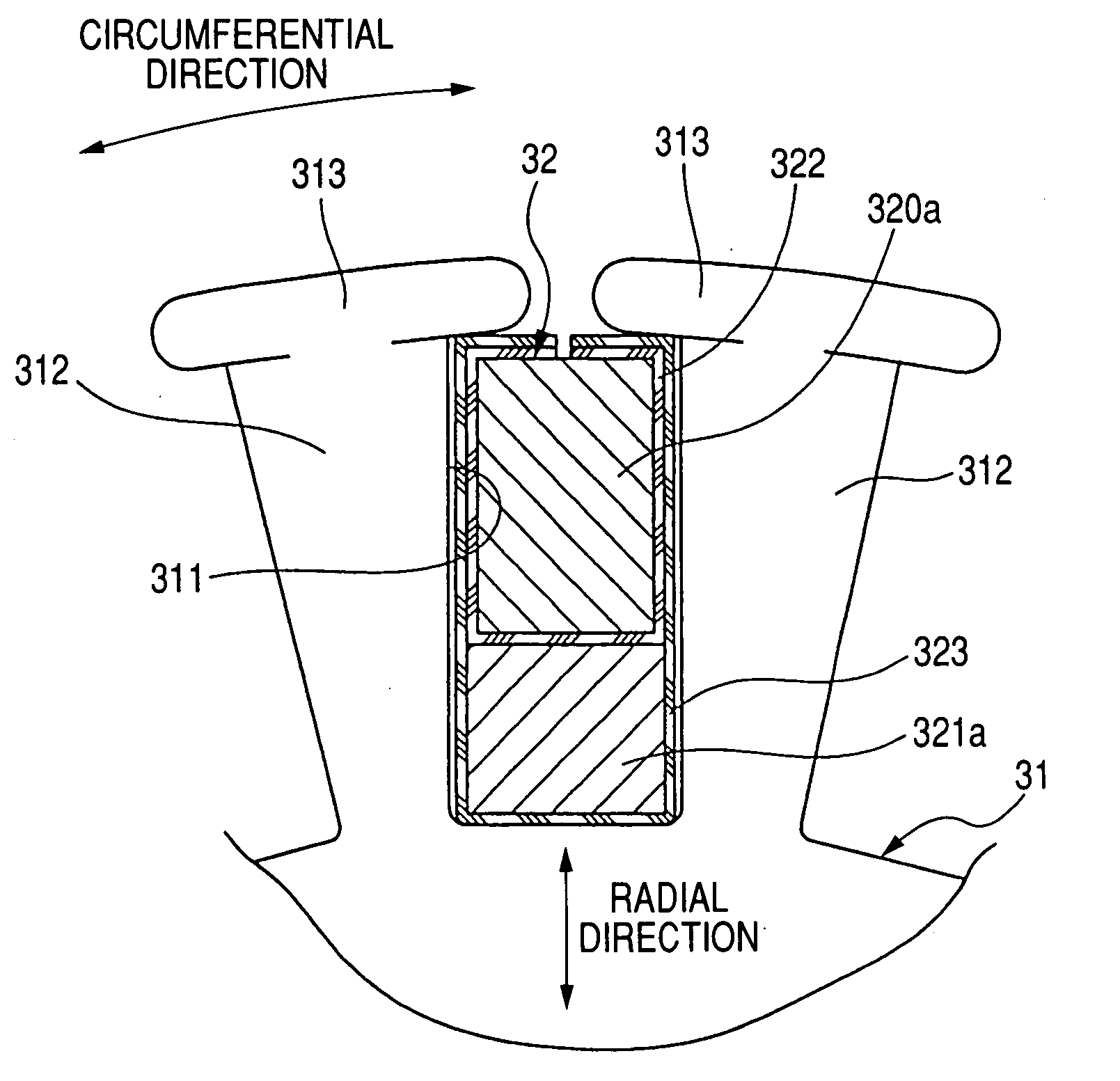
[0019]Further, the coil is heated due to an electric resistance of the coil in response to the current flowing through the coil, and heat of the coil is dissipated through the core having a large heat capacity. Because the upper layer coil part received in each slot are placed further away from the center axis of the core than the lower layer coil part received in the slot, the upper layer coil part is inferior to the lower layer coil part in heat dissipation. In contrast, because a sectional area of the upper layer coil part received in each slot is larger than a sectional area of the lower layer coil part received in the slot, an electric resistance of the upper layer coil part is lower than that of the lower layer coil part so as to set an amount of heat generated in the upper layer coil part to be lower than that generated in the lower layer coil part.
[0020]Therefore, although the upper layer coil part is inferior in heat dissipation, an increase of the temperature of the upper layer coil part can be set to be substantially equal to an increase of the temperature of the lower layer coil part. Accordingly, the machine can reliably reduce a temperature rise in the armature coil without enlarging a size of the machine, and the machine requires no insulating film having a high heat resistance for insulating the upper and lower layer coil parts and the core from one another.

Problems solved by technology

Therefore, because a heat dissipation performance for the upper layer coil side portions is degraded as compared with that for the lower layer coil side portions, the upper layer coil side portions generating heat larger than heat of the lower layer coil side portions are undesirably heated to a high temperature.
However, when an insulating film having a high heat resistance is used for the armature coil, a cost of the machine is undesirably heightened.

Method used


Image

  • Electric rotating machine with armature coil
  • Electric rotating machine with armature coil
  • Electric rotating machine with armature coil

Examples


embodiment 1

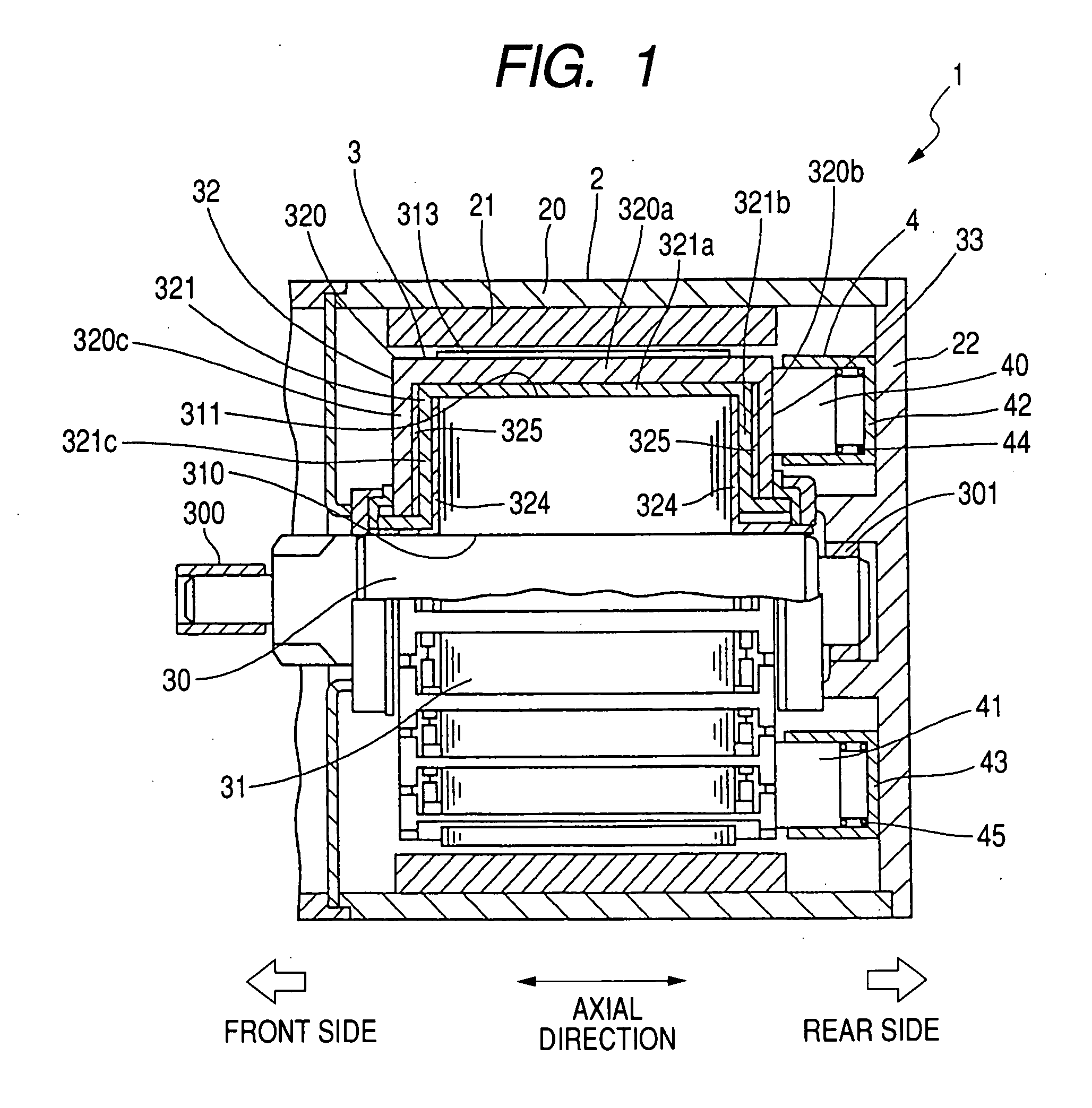
[0032]A structure of an electric rotating machine is now described with reference to FIG. 1. FIG. 1 is a longitudinal sectional view, with portions broken away, of an electric rotating machine, taken substantially along an axial direction of the machine.

[0033]An electric rotating machine is, for example, disposed on a vehicle to produce a rotational force from electric power as a motor of a starter or to produce electric power from a rotational force as a generator. As shown in FIG. 1, an electric rotating machine 1 has a stator 2 formed almost in a cylindrical shape, a rotor 3 disposed in a center space of the stator 2, a brush apparatus 4 disposed on a rear side of the stator 2 to supply an electric current to the rotor 3, and an end frame 22 to which the apparatus 4 is fixed.

[0034]The rotor 3 has a columnar shaft 30 rotatably supported by the frame 22 through bearings 300 and 301, an armature core 31 formed in a columnar shape and fixed to the shaft 30 so as to be rotated with th...

embodiment 2

[0063]In a second embodiment, sectional shapes of slots and slot-received portions of the coil 32 are modified.

[0064]FIG. 8 is a sectional view of slot-received portions of the coil 32 received in one slot 311 of the armature core 31 according to a second embodiment.

[0065]As shown in FIG. 8, the core 31 has a plurality of slots 340 in place of the slots 311. The slots 340 differs from the slots 311 in that each slot 340 is formed in a U shape in section. More specifically, a wall of the core 32 is rounded at a bottom of each slot 340 nearest to the shaft 30 so as not to form any corner in the slot 340. A sectional shape of the slot 340 is partitioned into an upper region having a square shape in section and a lower region having a semicircle and rectangular shape in section.

[0066]Each coil part 320 of the coil 32 has a slot-received portion (or intermediate portion) 350a and the two linking portions 320b and 320c. The portion 350a is formed in a bar shape and almost in a square in s...


PUM


Abstract

An electric rotating machine has a stator generating a magnetic flux and a rotor with a columnar armature core and an armature coil wound on the core. The flux passes through the rotor. The rotor is rotatable around its center axis. The core has slots aligned along its circumferential direction. Each slot extends along an axial direction of the core. The coil has upper layer coil parts and lower layer coil parts alternately connected with one another. Each pair of upper and lower layer coil parts is received in one slot so as to place the lower layer coil part nearer to the center axis of the core than the upper layer coil part. A sectional area of the upper layer coil part received in each slot is larger than a sectional area of the lower layer coil part received in the slot.

Description

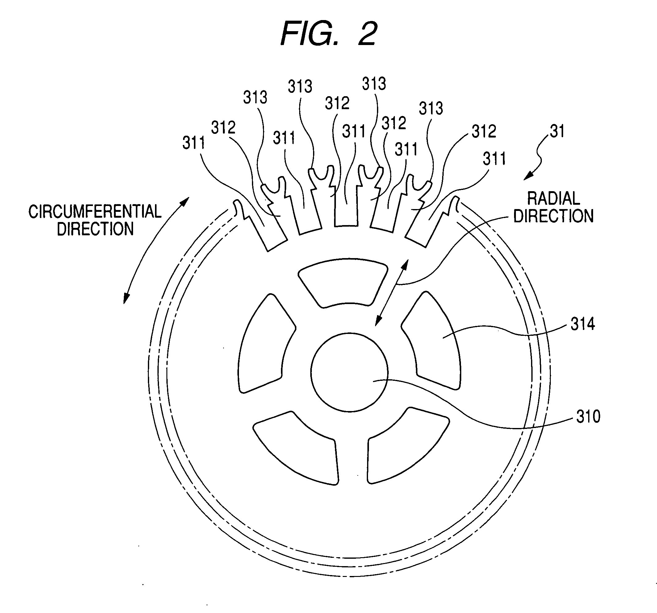
CROSS-REFERENCE TO RELATED APPLICATION[0001]This application is based upon and claims the benefit of priority of the prior Japanese Patent Application 2006-314686 filed on Nov. 21, 2006 so that the contents of which are incorporated herein by reference.BACKGROUND OF THE INVENTION[0002]1. Field of the Invention[0003]The present invention relates to an electric rotating machine wherein a rotor with an armature coil is rotated in response to an electric current flowing through the armature coil, or a current is generated in the armature coil in response to a rotation of the rotor caused by an external force.[0004]2. Description of Related Art[0005]An electric rotating machine has a cylindrical stator having fixed magnetic poles aligned along a circumferential direction thereof, a columnar rotor with an armature coil, and a yoke holding the stator. The rotor is disposed within a center space of the stator with an opening between the rotor and the stator. When an electric current flows t...

Claims


Application Information

Patent Timeline
IPC IPC(8): H02K3/48H02K1/26
CPCH02K13/08H02K3/12
Inventor HOSOYA, AKIFUMIKURASAWA, TADAHIROANDOH, KAZUHIRO
Owner DENSO CORP
Learn More