Perimeter

a technology of perimeter and meter, which is applied in the field of perimeter, can solve the problems of inability to accurately measure the visual field, long inspection time, and large burden on the subject, and achieve the effect of short time and accurate measurement of the visual field

Inactive Publication Date: 2008-05-22
MATSUSHITA ELECTRIC WORKS LTD
View PDF2 Cites 67 Cited by
  • Summary
  • Abstract
  • Description
  • Claims
  • Application Information

AI Technical Summary

Benefits of technology

[0007]In view of the above problem, the object of the present invention is to provide an objective perimeter capable of adjusting the background luminance, the brightness of the eye-target, and the size of the eye-target and so on easily and capable of measuring the visual field accurately in a short time.

Problems solved by technology

In such a subjective examination, there was a problem that an inspection result is easily swayed by a physical condition and concentration and so on of the subject and an accurate examination can not be done.
Furthermore, because a series of operations of showing the eye-target and then having the subject answer have to be repeated many times, there are also problems that it takes a long time to do the inspection and a burden on the subject is large.
But, when the background luminance is too dark, the light of the light stimulus eye-target is scattered, and therefore the light stimulus is not given to an accurate position of the retina of the subject.
Furthermore, it takes a long time for the pupil of the subject to adapt to the darkness of the background, whereby the inspection time becomes long.
On the other hand, when the background luminance is too bright, the brightness difference between the background and the light stimulus eye-target becomes small, and the pupillary light reflex also becomes small, and therefore, the detection of the reaction becomes difficult.
But, in the above mentioned conventional perimeter, because the eye-target is projected on a screen or the light stimulus eye-target is shown by using a light-emitting diode, there was a problem that it is not possible to easily adjust the background luminance, the brightness of the eye-target, and the size of the eye-target.

Method used


Image

  • Perimeter
  • Perimeter
  • Perimeter

Examples


Embodiment Construction

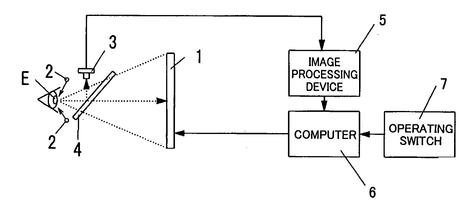
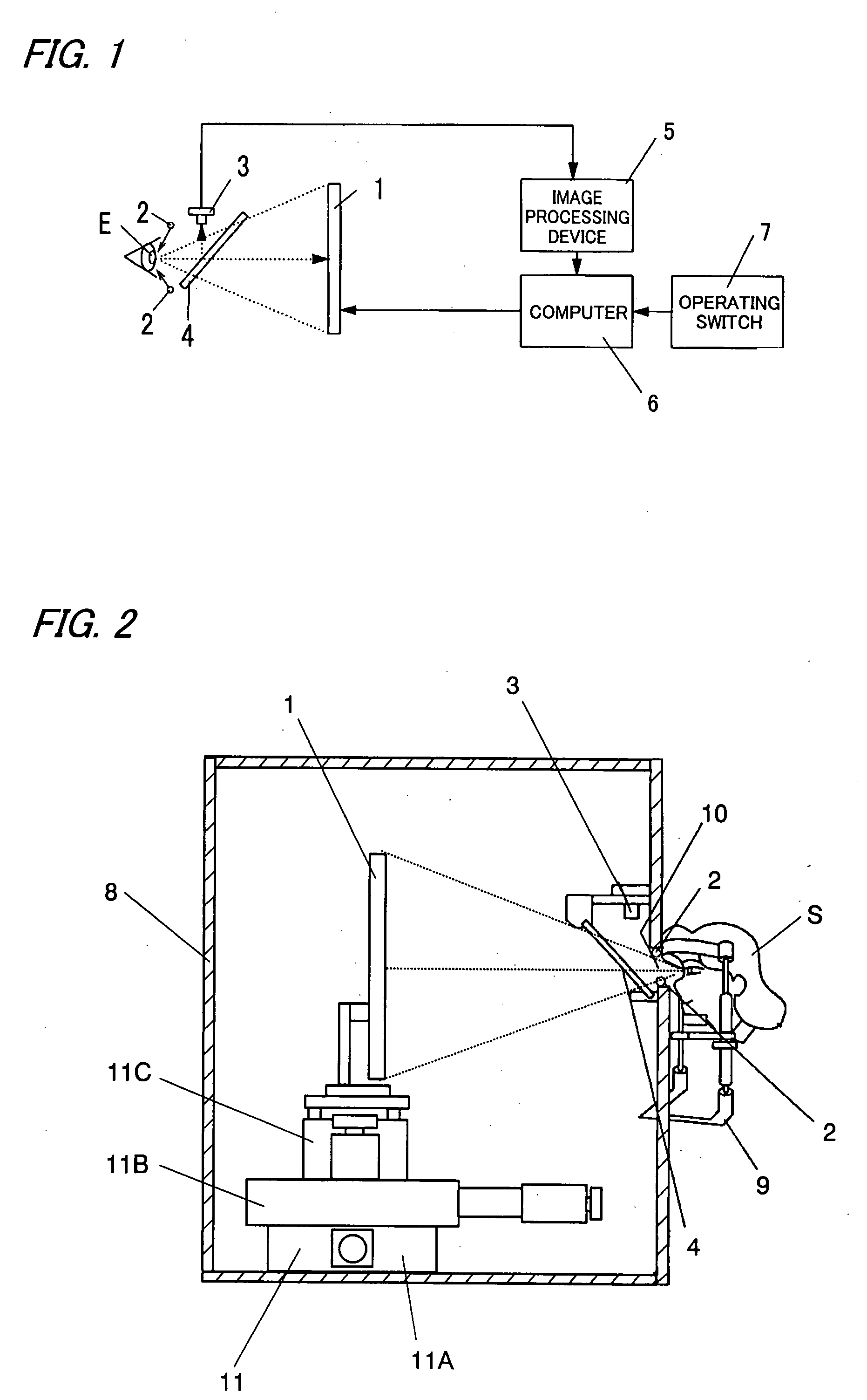
[0043]Hereinafter, the present invention will be described in more detail with reference to the accompanying drawings. FIG. 1 is a view showing a constitution of a perimeter of this embodiment. The perimeter comprises a liquid-crystal display 1, infrared light-emitting diodes 2, a CCD camera 3, a half mirror 4, an image processing device 5, a computer 6, and an operating switch 7. As shown in FIG. 2, the liquid-crystal display 1, the infrared light-emitting diode 2, the CCD camera 3, and the half mirror 4 are housed in a box-shaped case 8. The case 8 has, in one side surface, a peephole 10 through which a subject looks at the liquid-crystal display 1 installed in the case 8, and a jaw supporting base 9 for supporting a jaw of the subject is installed on the side surface.

[0044]The liquid-crystal display 1 (a display means) shows a fixed eye-target F for fixing a line of sight of the subject and a light stimulus eye-target L for giving a light stimulus to a pupil of the subject. A sho...


PUM


Abstract

The perimeter comprises a display device 1, infrared light-emitting diodes 2, a CCD camera 3, a half mirror 4, an image processing device 5, a computer 6, and an operating switch 7. The computer 6 shows a fixed eye-target for fixing a line of sight of a subject and a light stimulus eye-target for giving a light stimulus to a pupil of the subject at a plurality of predetermined positions on the display device 1. The infrared light-emitting diodes 2 irradiate infrared light to an eye of the subject. The CCD camera 3 takes an image of the eye of the subject using the infrared light irradiated from the infrared light-emitting diodes 2. The image processing device 5 detects a pupil diameter of the subject based on the image taken by the CCD camera 3. The computer 6 measures a visual field of the subject based on the change of the pupil diameter of the subject detected by the image processing device 5. The feature of the present invention resides in that the display device 1 comprises a display device capable of adjusting background luminance of a screen and brightness of the light stimulus eye-target separately.

Description

TECHNICAL FIELD[0001]The present invention relates to a perimeter for measuring a visual field of a subject.BACKGROUND ART[0002]Examination of visual field (namely, a perimetry) is performed to diagnose a constriction of visual field which is a symptom of glaucoma and so on. In the conventional perimetry, the visual field of the subject is measured by showing an eye-target at a specific point in front of an eye of a subject and having the subject answer a question whether he or she can see the eye-target. Such an examination is a subjective examination based on a subjective answer of the subject, and a visual field range of the subject is identified by measuring the visual field multiple times while changing the showing position of the eye-target one after another. In such a subjective examination, there was a problem that an inspection result is easily swayed by a physical condition and concentration and so on of the subject and an accurate examination can not be done. Furthermore,...

Claims


Application Information

Patent Timeline
Patent Type & Authority Applications(United States)
IPC IPC(8): A61B3/02
CPCA61B3/111A61B3/0091A61B3/112
Inventor INAKAGATA, SATORUMURAKAMI, SHUJIFUKUSHIMA, SHOGOFUKUNAGA, HIDEOTABUCHI, AKIOKANI, KAZUTAKAMAEDA, FUMIATSU
Owner MATSUSHITA ELECTRIC WORKS LTD
Why Eureka
Try Eureka