
System for improved backlight illumination uniformity

a backlight illumination and uniformity technology, applied in lighting and heating apparatuses, lighting device details, instruments, etc., can solve the problems of increased non-uniformity of illumination under the lcd screen, ccfls with relatively low luminous efficiency, and occupying more space, so as to increase luminance uniformity, reduce banding, and increase luminance uniformity

Inactive Publication Date: 2008-05-22
GENERAL ELECTRIC CO
View PDF24 Cites 17 Cited by
  • Summary
  • Abstract
  • Description
  • Claims
  • Application Information

AI Technical Summary

Benefits of technology

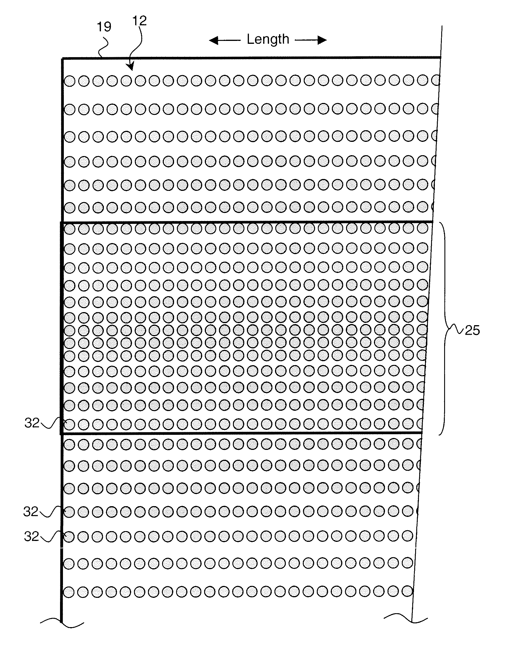
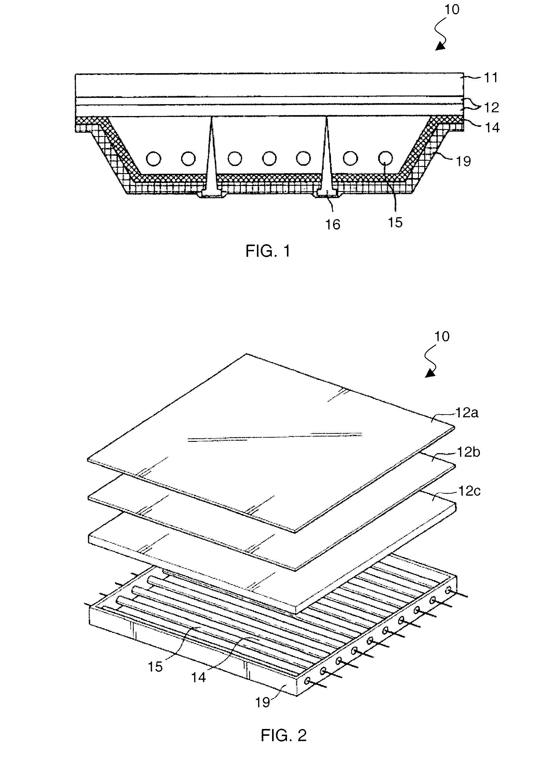
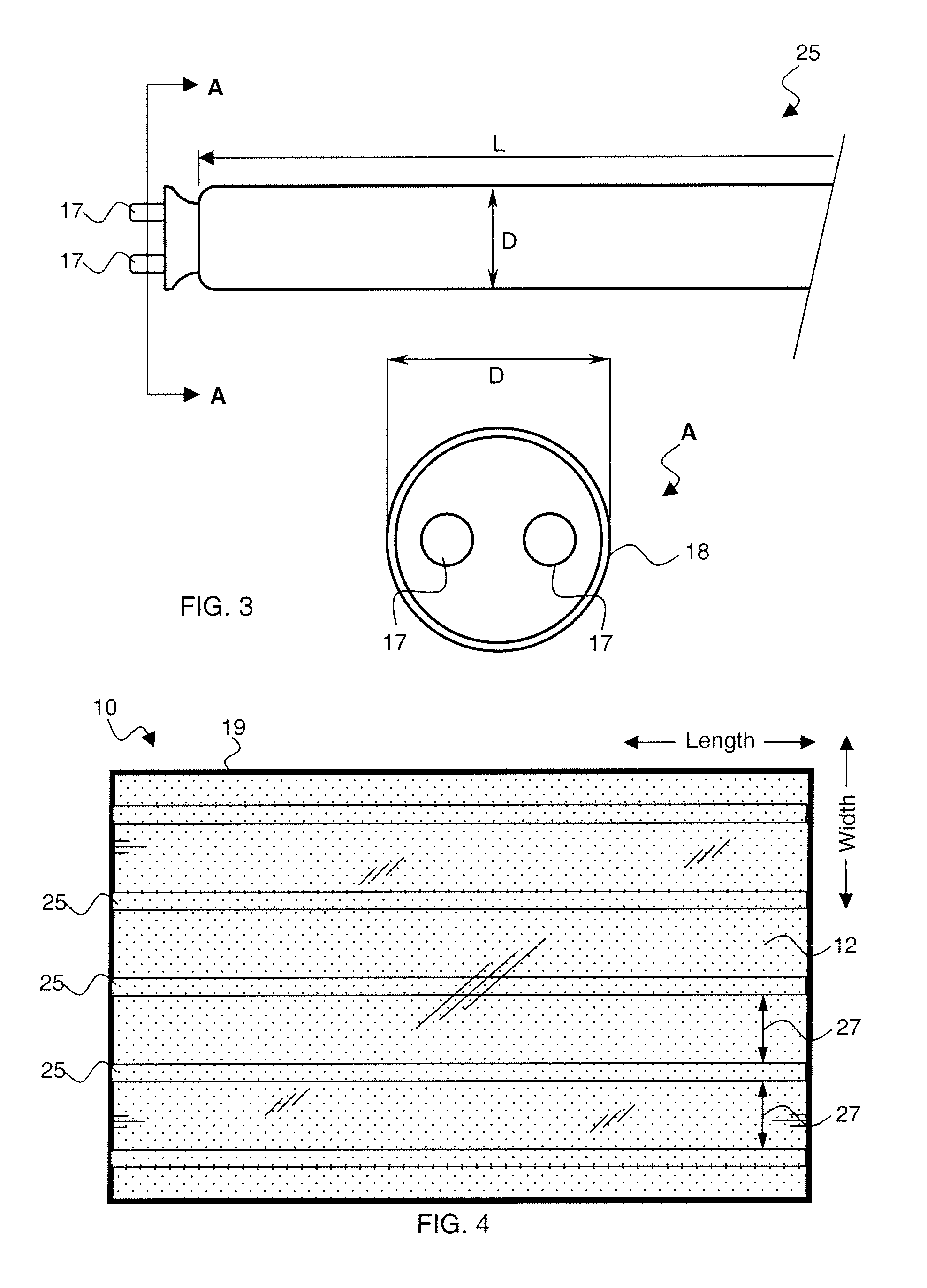
[0004]In one embodiment, an illumination system includes a backlight housing, a plurality of light valves coupled to the backlight housing, and a plurality of light sources arranged in the backlight housing and optically coupled to the light valves. The illumination system may further include a light-scattering substrate optically coupled between the plurality of light sources and the light valves, and a plurality of light modulating dots patterned on the substrate to modulate transmitted intensity of light from the plurality of light sources to achieve increased luminance uniformity by decreasing banding caused by the separated light sources.
[0005]In another embodiment an optical diffuser includes a light-scattering substrate and a plurality of light modulating dots patterned on the substrate to modulate transmitted intensity of light from a light source to achieve increased luminance uniformity by decreasing banding caused by widely separated light.

Problems solved by technology

Although CCFLs have small form factors (with diameters typically in the 2.6 to 3.0 mm range) CCFLs have relatively low luminous efficiency and are fragile at longer lengths.
However, since the trend in flat panel displays is to reduce panel depth and HCFLs have larger diameters than CCFLs, the HCFLs tend to occupy more space within the backlight cavities of the display panels.
This causes greater non-uniformity in the illumination under the LCD screen in the form of banding, which is generally objectionable to end users.

Method used


Image

  • System for improved backlight illumination uniformity
  • System for improved backlight illumination uniformity
  • System for improved backlight illumination uniformity

Examples


Embodiment Construction

[0015]In accordance with one or more embodiments of the present invention, systems and methods for improving illumination uniformity are described herein. In the following detailed description, numerous specific details are set forth in order to provide a thorough understanding of various embodiments of the present invention. However, those skilled in the art will understand that embodiments may be practiced without these specific details, that the present invention is not limited to only the depicted embodiments, and that the present invention may be practiced in a variety of alternative embodiments. In other instances, well known methods, procedures, and components have not been described in detail. Moreover, repeated usage of the phrase “in one embodiment” does not necessarily refer to the same embodiment, although it may. Lastly, the terms “comprising”, “including”, “having”, and the like, as used in the present application, are intended to be synonymous unless otherwise indicat...


PUM


Abstract

An illumination system includes a backlight housing, a plurality of light valves coupled to the backlight housing, and a plurality of light sources arranged in the backlight housing and optically coupled to the light valves. The illumination system may further include a light-scattering substrate optically coupled between the plurality of light sources and the light valves, and a plurality of light modulating dots patterned on the substrate to modulate transmitted intensity of light from the plurality of light sources to achieve increased luminance uniformity by decreasing banding caused by the separated light sources. The light modulating dots may include comprise reflective dots, transmissive dots, absorptive dots, or a combination thereof.

Description

BACKGROUND[0001]Embodiments of the invention relate generally to a system for improved backlight illumination uniformity in display devices.[0002]Large format display devices, such as flat panel liquid crystal displays (LCDs) typically utilize cold cathode fluorescent lamps (CCFL) as light sources. Although CCFLs have small form factors (with diameters typically in the 2.6 to 3.0 mm range) CCFLs have relatively low luminous efficiency and are fragile at longer lengths. As display panel screen diagonals continue to increase there is also an increasing need for mechanically robust, high luminous efficiency light sources to illuminate such displays.[0003]More recently, hot cathode fluorescent lamps (HCFL) have been used as light sources for such flat panel displays. The use of HCFL's allows for current pulsing of the light output which allows for the reduction of motion blur caused by the finite lag time for the LCD pixel to change state between image frames. HCFLs further provide high...

Claims


Application Information

Patent Timeline
Patent Type & Authority Applications(United States)
IPC IPC(8): F21V5/00G02B26/08
CPCG02F1/133611G02F1/133604G02F1/1335
Inventor DURVASULA, RAVI SHANKARMEYERS, MARK MARSHALLLORRAINE, PETER WILLIAM
Owner GENERAL ELECTRIC CO
Learn More