Novel Method of Reducing High Voltage Arcs in X-Ray Tubes

a technology of x-ray tubes and high-voltage arcs, which is applied in the direction of x-ray tubes, x-ray tube gas control, mechanical equipment, etc., can solve the problem of compromising the ability of solid metal lubricant to adhere to the balls

Inactive Publication Date: 2008-05-22
VARIAN MEDICAL SYSTEMS
View PDF7 Cites 5 Cited by
  • Summary
  • Abstract
  • Description
  • Claims
  • Application Information

AI Technical Summary

Benefits of technology

[0021] The present invention has been developed in response to the current state of the art, and in particular, in response to these and other problems and needs that have not been fully or adequately resolved by currently available bearing assemblies. Briefly summarized, embodiments of the present invention provide a bearing assembly which includes features directed toward facilitating improved control of foreign matter generated or present within, or without, the bearing assembly.
[0022] Embodiments of the present invention are particularly well suited for use in the context of rotating anode type x-ray tubes. However, it will be appreciated that embodiments of the present invention may be suitable for use in any device where it is desired to effectively and reliably control foreign matter so as to prevent damage to the bearing assembly and / or to the device.

Problems solved by technology

Such foreign particles compromise the ability of the solid metal lubricant to adhere to the balls and races.

Method used


Image

  • Novel Method of Reducing High Voltage Arcs in X-Ray Tubes
  • Novel Method of Reducing High Voltage Arcs in X-Ray Tubes
  • Novel Method of Reducing High Voltage Arcs in X-Ray Tubes

Examples


Embodiment Construction

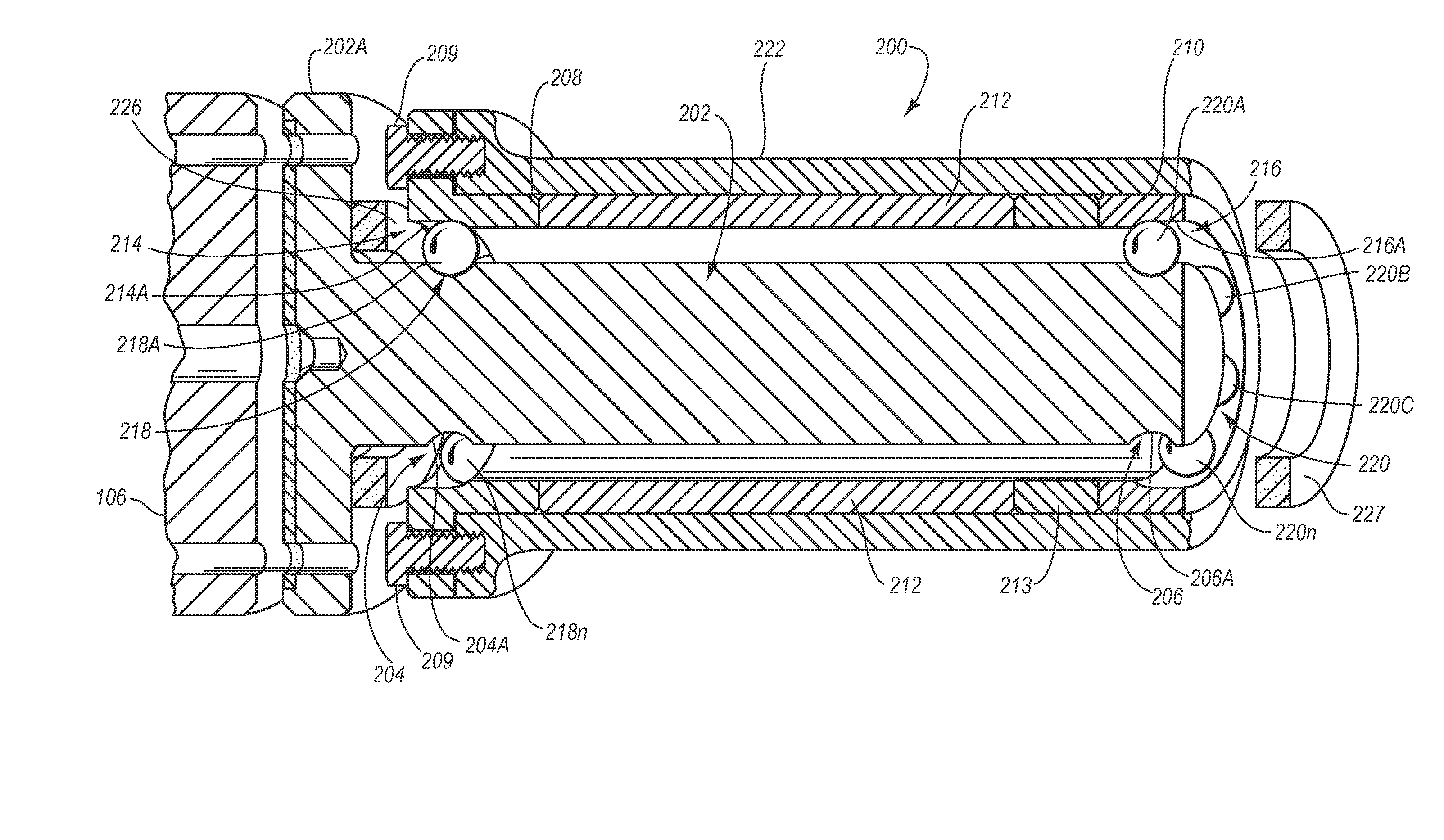
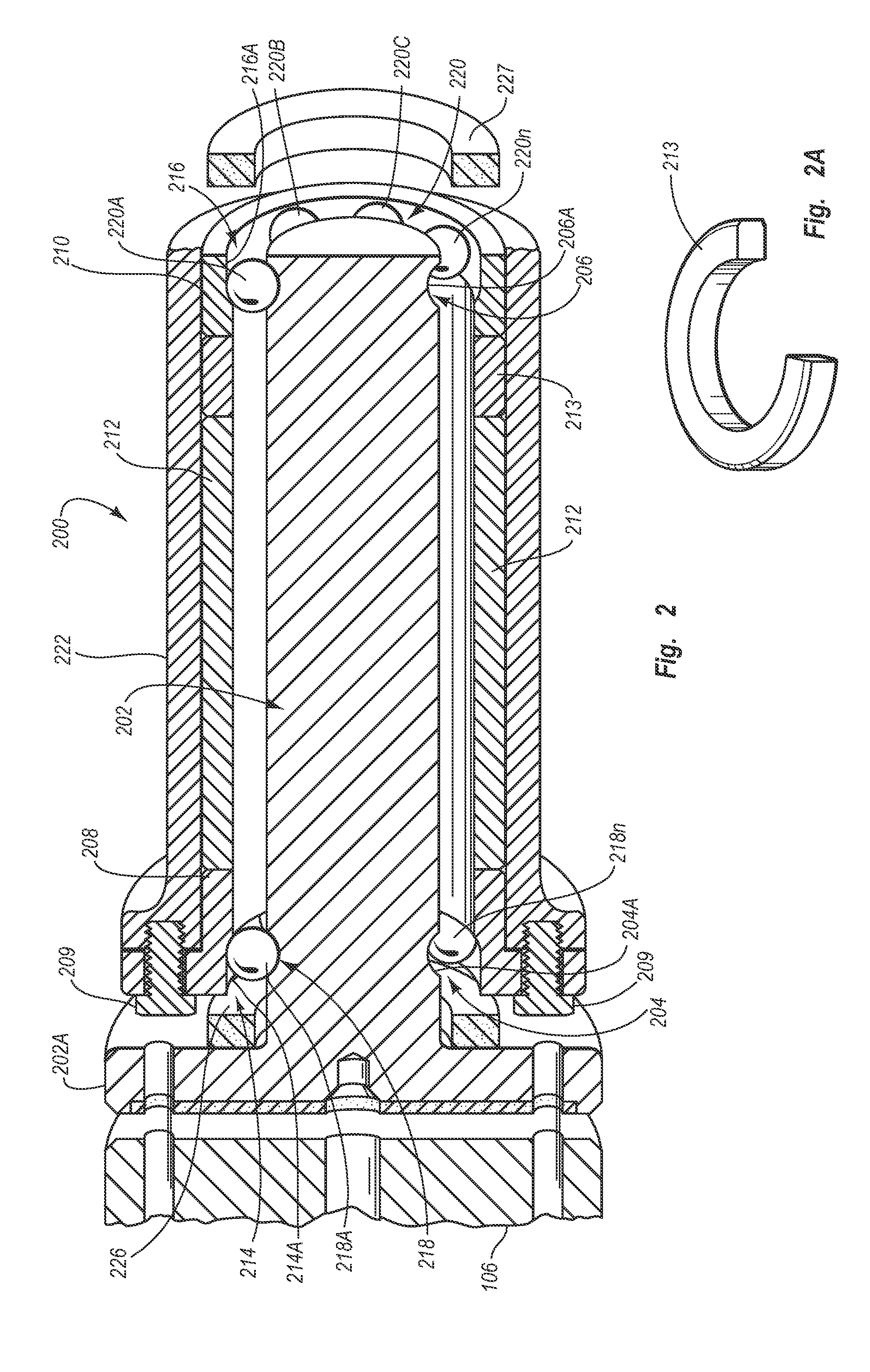
[0036] Reference will now be made to figures wherein like structures will be provided with like reference designations. It is to be understood that the drawings are diagrammatic and schematic representations of various embodiments of the invention, and are not to be construed as limiting the present invention, nor are the drawings necessarily drawn to scale.

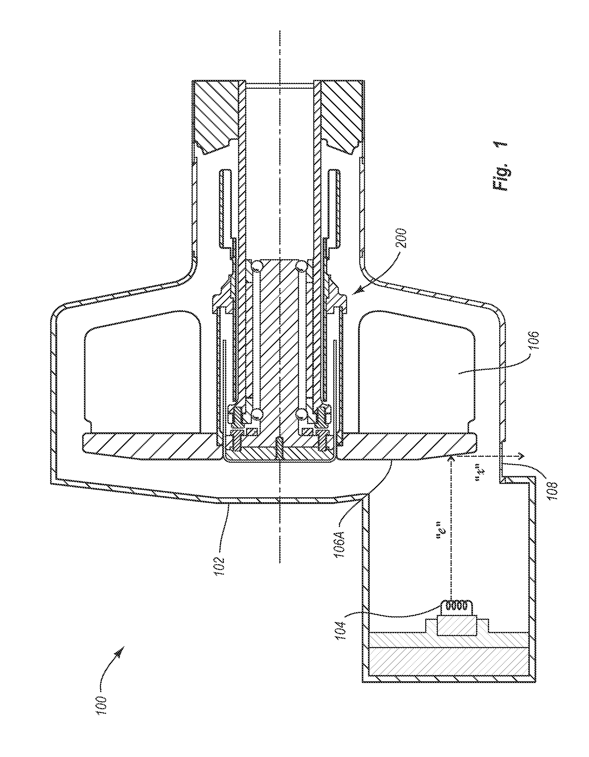
[0037] Reference is first made to FIG. 1, wherein an x-ray tube is indicated generally at 100. It will be appreciated that the x-rays produced by x-ray tube 100 may be employed in any of a variety of applications, and embodiments of the present invention should accordingly not be construed to be limited to any particular field of application.

[0038] As indicated in the illustrated embodiment, x-ray tube 100 includes a vacuum enclosure 102, inside which is disposed an electron source 104, preferably comprising a cathode or the like, and an anode 106 arranged in a spaced-apart configuration with respect to electron source 104 and ...


PUM


Abstract

A bearing assembly suitable for use in conjunction with x-ray device having a rotating target anode and electron source disposed in an evacuated enclosure. The bearing assembly includes a shaft having a rotor hub to which the anode is mounted. The shaft cooperates with front and rear bearing rings to define front and rear races, and a spacer facilitates positioning of the bearing rings. Front and rear ball sets are confined in the front and rear races, respectively. A bearing housing receives the bearing rings, spacer, front and rear ball sets, and part of the shaft. Finally, a magnet is disposed near the front bearing ring to prevent escape of foreign matter from the bearings and to prevent ingress of foreign matter to the bearings. Consequently, the magnet serves to extend the life of the bearings and to prevent foreign matter related arcing of the target anode and electron source.

Description

CROSS-REFERENCE TO RELATED APPLICATIONS [0001] The present application is a continuation of U.S. patent application Ser. No. 10 / 358,940 filed on Feb. 5, 2003; which is incorporated herein by reference in its entirety.BACKGROUND OF THE INVENTION [0002] 1. The Field of the Invention [0003] The present invention relates generally to systems and devices that include at least one component rotatably supported by a bearing assembly. More particularly, embodiments of the present invention relate to bearing assemblies that include various features directed to controlling ingress and egress of foreign matter to and from, respectively, the bearing assembly, and which thereby materially reduce the incidence of foreign matter related problems in the bearing assembly, as well as in the system or device wherein the bearing assembly is employed. [0004] 2. Related Technology [0005] X-ray producing devices are valuable tools that are used in a wide variety of industrial, medical, and other applicati...

Claims


Application Information

Patent Timeline
Patent Type & Authority Applications(United States)
IPC IPC(8): H01J35/00H05G1/00F16C33/82
CPCF16C33/66F16C33/82H01J35/101F16C2380/16H01J2235/108H01J2235/20H01J2235/1046H01J35/103
Inventor LEE, DAVID S.K.POSTMAN, JOHN E.
Owner VARIAN MEDICAL SYSTEMS
Why Eureka
Try Eureka