Control of stray light in camera systems employing an optics stack and associated methods

a technology of optic stack and control method, applied in the field of camera system, can solve the problems of internal reflection of side light increasing noise, external light entering from the side may increase noise,

Inactive Publication Date: 2008-05-22
DIGITALOPTICS CORPORATION
View PDF14 Cites 248 Cited by
  • Summary
  • Abstract
  • Description
  • Claims
  • Application Information

AI Technical Summary

Benefits of technology

[0006]It is therefore a feature of the present invention to provide a material preventing external stray light from reaching a detector of the camera system.
[0...

Problems solved by technology

In other words, light entering from the sides externally may increase...

Method used


Image

  • Control of stray light in camera systems employing an optics stack and associated methods
  • Control of stray light in camera systems employing an optics stack and associated methods
  • Control of stray light in camera systems employing an optics stack and associated methods

Examples


first embodiment

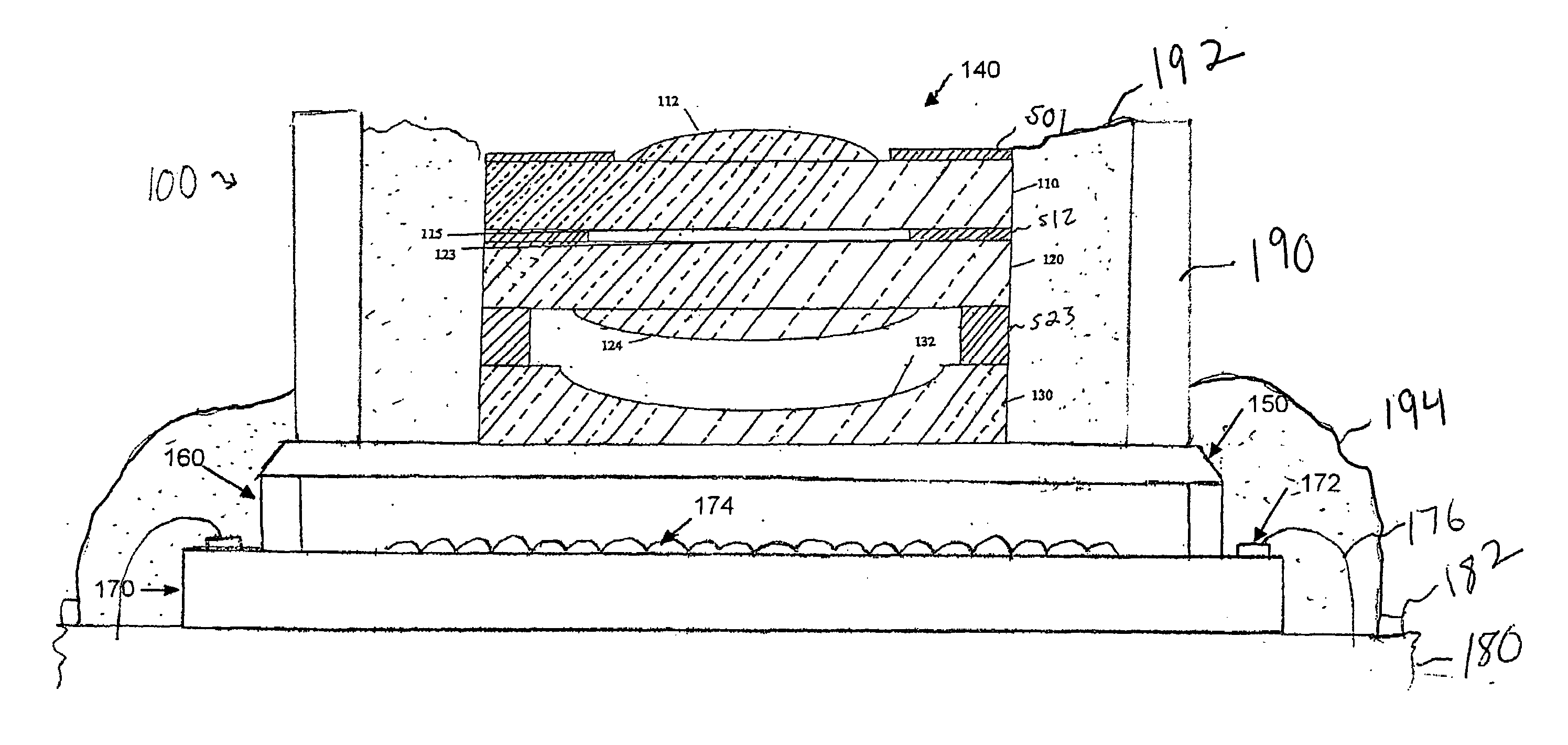
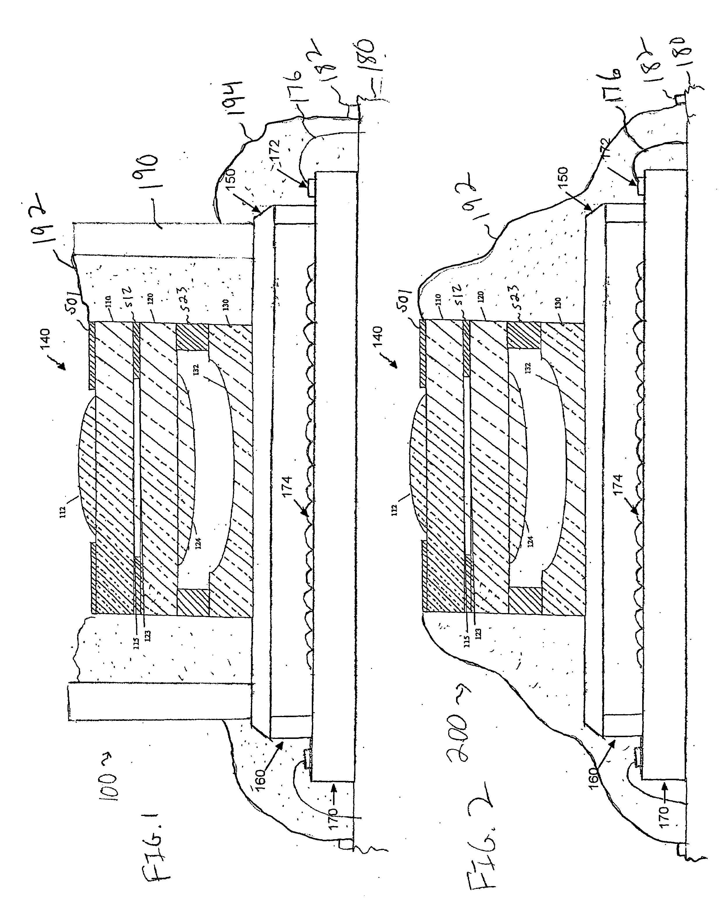
[0035]A camera system 100 in accordance with the present invention is shown in FIG. 1. In FIG. 1, a single lens system may be used for all colors, and a color filter may be provided directly on a detector array. Alternatively, this lens system may be provided in any number, e.g., three or four, of sub-cameras for each camera system, while a design and / or location of the color filters may be varied. Such lens stack designs for a camera may be found, for example, in commonly assigned, co-pending U.S. Provisional Patent Application No. 60 / 855,365 filed Oct. 31, 2006 and U.S. patent application Ser. No. 11 / 487,580, filed Jul. 17, 2006, and Ser. No. 10 / 949,807, filed Sep. 27, 2004, all of which are hereby incorporated by reference in their entirety.

[0036]As illustrated in FIG. 1, the camera system 100 according to the first embodiment of the present invention may include an optics stack 140 and a detector substrate 170. The optics stack 140 may include a first substrate 110, a second sub...

sixth embodiment

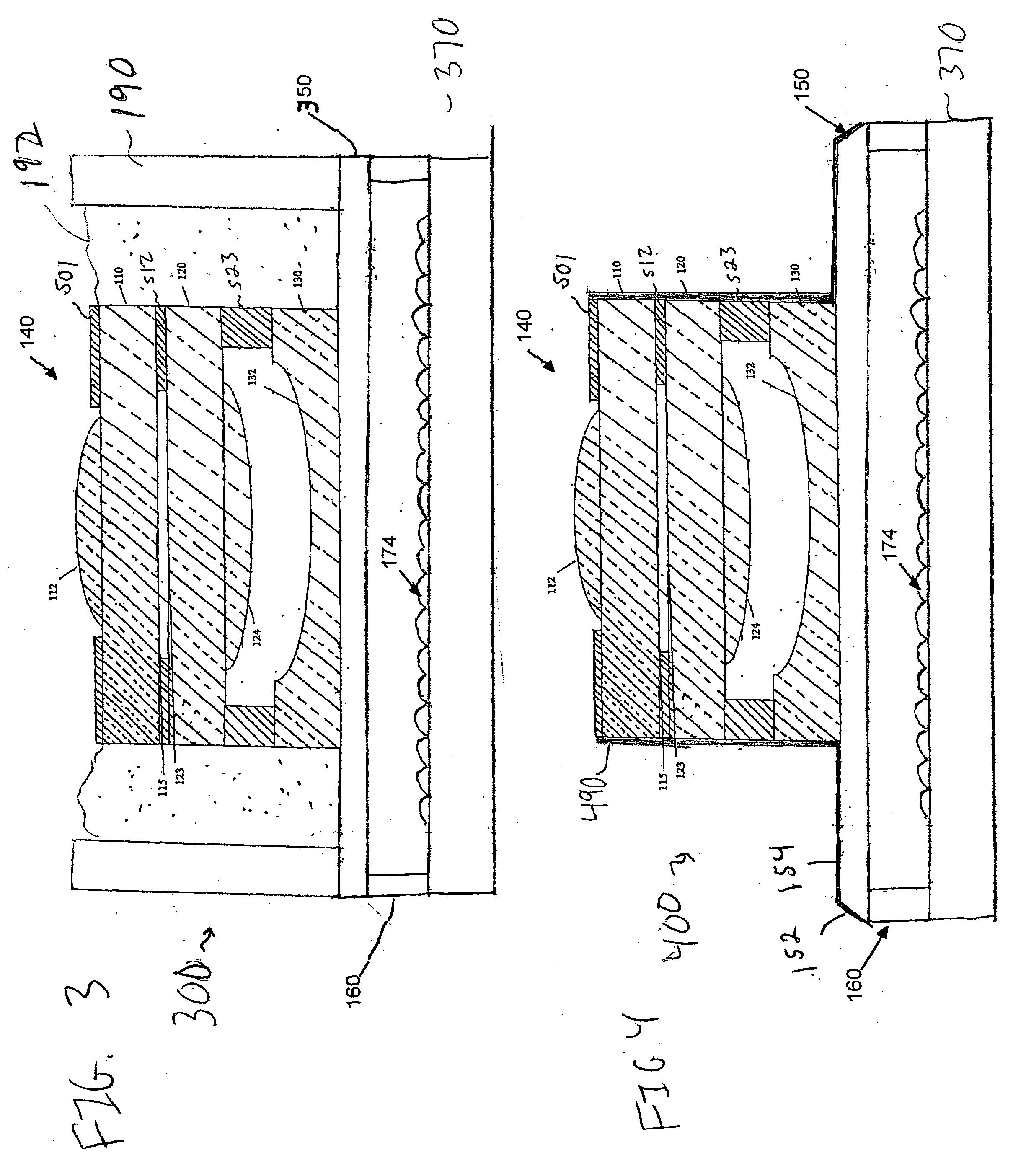
[0055]In a camera system 600 as illustrated in FIG. 6, a housing 690, e.g., an opaque housing, may protect the wire bonds 176 as well as contain an encapsulant material 692. A first substrate 610 of an optics stack 640 may have a smaller surface area than the second and third substrates 620, 630. The second substrate 620 may include features to further aid in restraining the encapsulant 692. The resultant stepped structure of optics stack 640 may be formed, for example, by securing a singulated first substrate to secured second and third substrates or by securing all three substrates before singulation, and singulating by dicing, e.g., with different blade widths from different surfaces of the secured substrates. Here, the encapsulant 692 may also serve to hermetically seal the camera system 600. The optics stack 640, as with any of the other embodiments, may be any suitable optics stack.

[0056]In a camera system 700 according to the seventh embodiment, as illustrated in FIG. 7, a s...


PUM


Abstract

A camera system may include an optics stack including two substrates secured together in a vertical direction and an optical system on the two substrates, the two substrates having exposed sides, a detector on a detector substrate, and a stray light blocker directly on at least some sides of the optics stack.

Description

FIELD OF THE INVENTION[0001]The present invention is directed to a camera system and associated methods. More particularly, the present invention is directed to a camera system including an optics stack having reduced stray light.BACKGROUND OF THE INVENTION[0002]Cameras may include an optics stack of optical substrates secured to one another at planar portions thereof. A plurality of these optics stacks may be made simultaneously, e.g., at a wafer level.[0003]Further, since the optical system may be formed of a vertical stack of substrates secured to one another, a housing, e.g., a barrel, may not be needed for mounting lenses in the optical system. While elimination of such a housing may provide many advantages, including increased simplicity and reduced cost, such an optical system itself may have transparent sides along which the stack was separated, e.g., diced, from a rest of a wafer.[0004]Such sides may allow light to enter the optics stack at other than the designed entrance ...

Claims


Application Information

Patent Timeline
IPC IPC(8): G03B17/00
CPCG02B27/0018H04N5/2257H04N5/2254H01L27/14618H01L2224/48091H04N23/57H04N23/55H01L2924/00014G03B17/12G02B7/021H05K1/111H05K1/14
Inventor TEKOLSTE, ROBERTMCWILLIAMS, BRUCEHAN, HONGTAOWELCH, WILLIAM HUDSON
Owner DIGITALOPTICS CORPORATION
Why Eureka
Try Eureka