Applicator device

a technology of a holder and a holder body, which is applied in the direction of hand holder, brushes, packaging goods, etc., can solve the problems of generally at least extremely difficult, if not impossible, refilling for users, etc., and achieve uniform and accurate line thicknesses, less flexible materials, and simple design.

Active Publication Date: 2008-05-22
SCHWAN STABILO COSMETICS
View PDF10 Cites 5 Cited by
  • Summary
  • Abstract
  • Description
  • Claims
  • Application Information

AI Technical Summary

Benefits of technology

[0007]The above-described dip system also enjoys the advantage that for example products of different colors can be applied with one and the same applicator device, simply by the desired color being mixed in the reservoir.
[0008]The applicator element in ball form, in the fashion of a ballpoint pen, has in particular the advantage of rotational symmetry in dip systems, in comparison with an applicator element in the form of a roller or wheel, as is described for example in EP 1498045 Al. That means that, in the operation of applying the product, there is no need to set a predetermined axis of rotation transversely with respect to the direction of application. In addition, a scraper which is possibly provide...

Problems solved by technology

More specifically refilling is generally at lea...

Method used


Image

  • Applicator device
  • Applicator device

Examples


Embodiment Construction

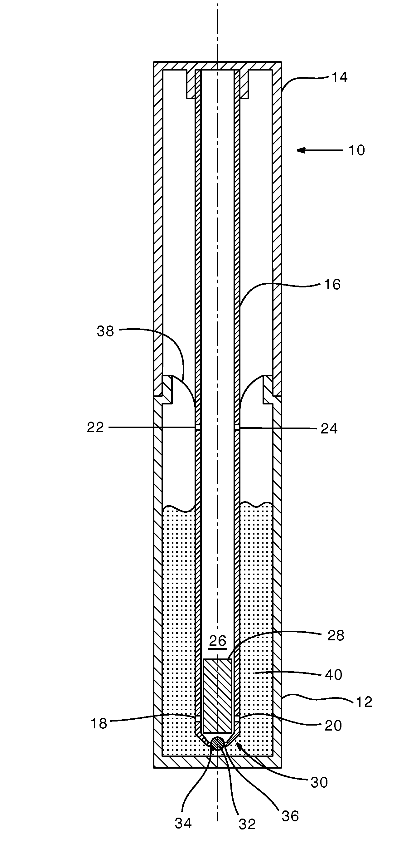
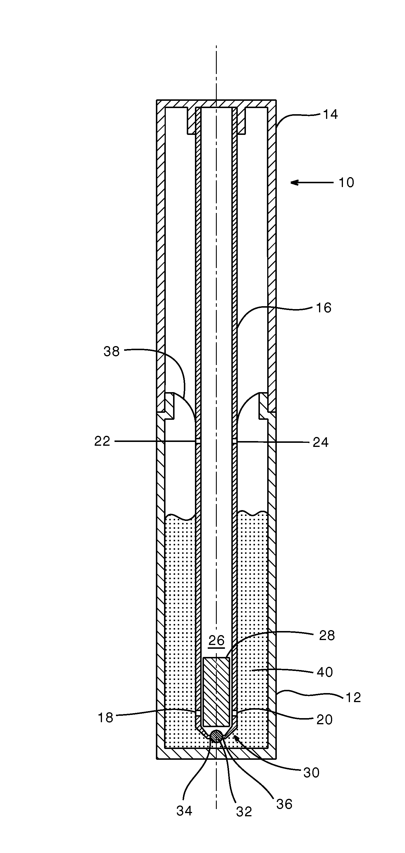
[0025]The cosmetic unit shown in the drawing includes an applicator device 10 and a container 12.

[0026]The applicator device has a holding portion 14 in which an internally hollow stem 16 fits. The stem has two feed openings 18, 20 and two vent openings 22, 24. The openings 18 through 24 connect an internal space 26 in the stem 16 to the ambient atmosphere around the stem. A puffer storage means 28 of an absorbent material, for example felt, is disposed in the region of the internal space 26, which is the lower region in the drawing.

[0027]A working end of the stem 16 or of the applicator device 10 is in the form of a holding device 30 (only diagrammatically shown in the drawing) for a ball 32 which is held freely rotatably by the holding device 30. Two passages 34, 36 are provided between the holding device 30 on the one hand and the ball 32 on the other hand, although this is also only diagrammatically illustrated in the drawing. The passages 34, 36 connect the internal space 26 of...


PUM


Abstract

A device for applying a liquid or gel-like product, in particular a cosmetic product, comprising a rotatably supported ball serving as an applicator element, and a storage chamber for the product to be applied on a side of the ball in opposite relationship to an applicator side of the ball for loading the ball on its side in opposite relationship to its applicator side, wherein the storage chamber has a feed opening for the product to be applied. A vent opening is disposed behind the feed opening as viewed from the ball for venting the storage chamber.

Description

BACKGROUND OF THE INVENTION[0001]The invention concerns a device for applying a liquid or gel-like product comprising a rotatably supported ball serving as an applicator element, and a storage chamber for the product to be applied on a side of the ball in opposite relationship to an applicator side of the ball for loading the ball on its side in opposite relationship to its applicator side, wherein the storage chamber has a feed opening for the product to be applied.[0002]Devices of the above-indicated kind are known in the form of ballpoint pens. In general a predetermined amount of the product is to be applied is stored in the storage chamber of such applicator devices. When the storage chamber is exhausted the ballpoint pen (or at least its refill) has to be thrown away. More specifically refilling is generally at least extremely difficult for a user, if not impossible.[0003]As the user does not usually himself fill the storage chamber with the product he also has no influence fo...

Claims


Application Information

Patent Timeline
IPC IPC(8): A45D34/04
CPCA45D34/041A45D40/16B43K11/00A45D40/261B43K7/00A45D40/20
Inventor BIEGEL, FRIEDRICH
Owner SCHWAN STABILO COSMETICS
Why Eureka
Try Eureka