Eureka AIR delivers breakthrough ideas for toughest innovation challenges, trusted by R&D personnel around the world.

Wide flow compressor with diffuser bypass

a compressor and diffuser technology, applied in the field of turbines, can solve the problems of cyclical flow instability, adversely affecting some other aspect of a compressor, and compressor design for a particular application typically requires expensive iterative design trials and modeling

Inactive Publication Date: 2008-05-22
HONEYWELL INT INC
View PDF6 Cites 11 Cited by
  • Summary
  • Abstract
  • Description
  • Claims
  • Application Information

AI Technical Summary

Problems solved by technology

Under surge conditions undesirable cyclical flow instability develops.
However, as is often the case with designs having interrelated parameters, changing one design variable may adversely affect some other aspect of a compressor.
Thus a compressor design for a particular application typically requires expensive iterative design trials and modeling.
Using a ported shroud to recycle the flow near the leading edge of a wheel of a compressor with a vaned diffuser may not improve its flow range.
To the contrary, a ported shroud may actually diminish the compressor's performance.
The phenomenon may produce cyclical surging of gas through the compressor 10 accompanied with harmful vibrational stresses

Method used


Image

  • Wide flow compressor with diffuser bypass
  • Wide flow compressor with diffuser bypass
  • Wide flow compressor with diffuser bypass

Examples


Embodiment Construction

[0022]The following detailed description is of the best currently contemplated modes of carrying out the invention. The description is not to be taken in a limiting sense, but is made merely for the purpose of illustrating the general principles of the invention, since the scope of the invention is best defined by the appended claims.

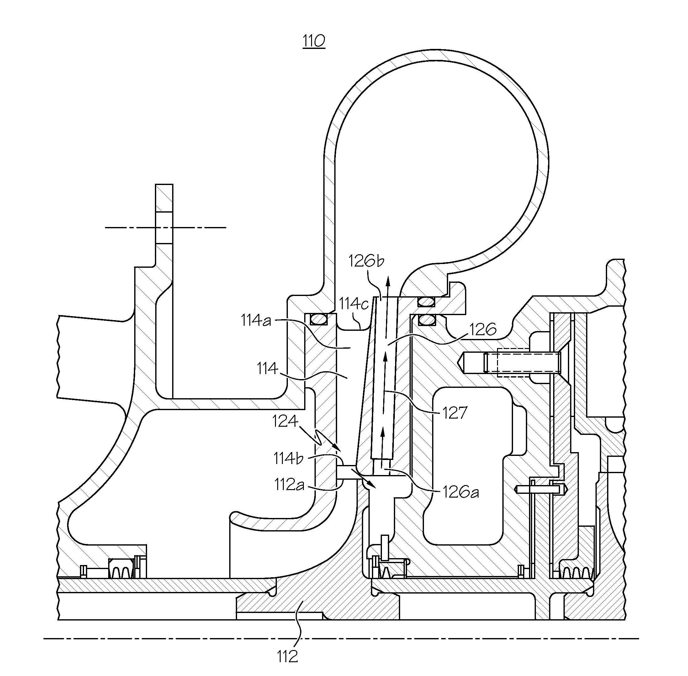
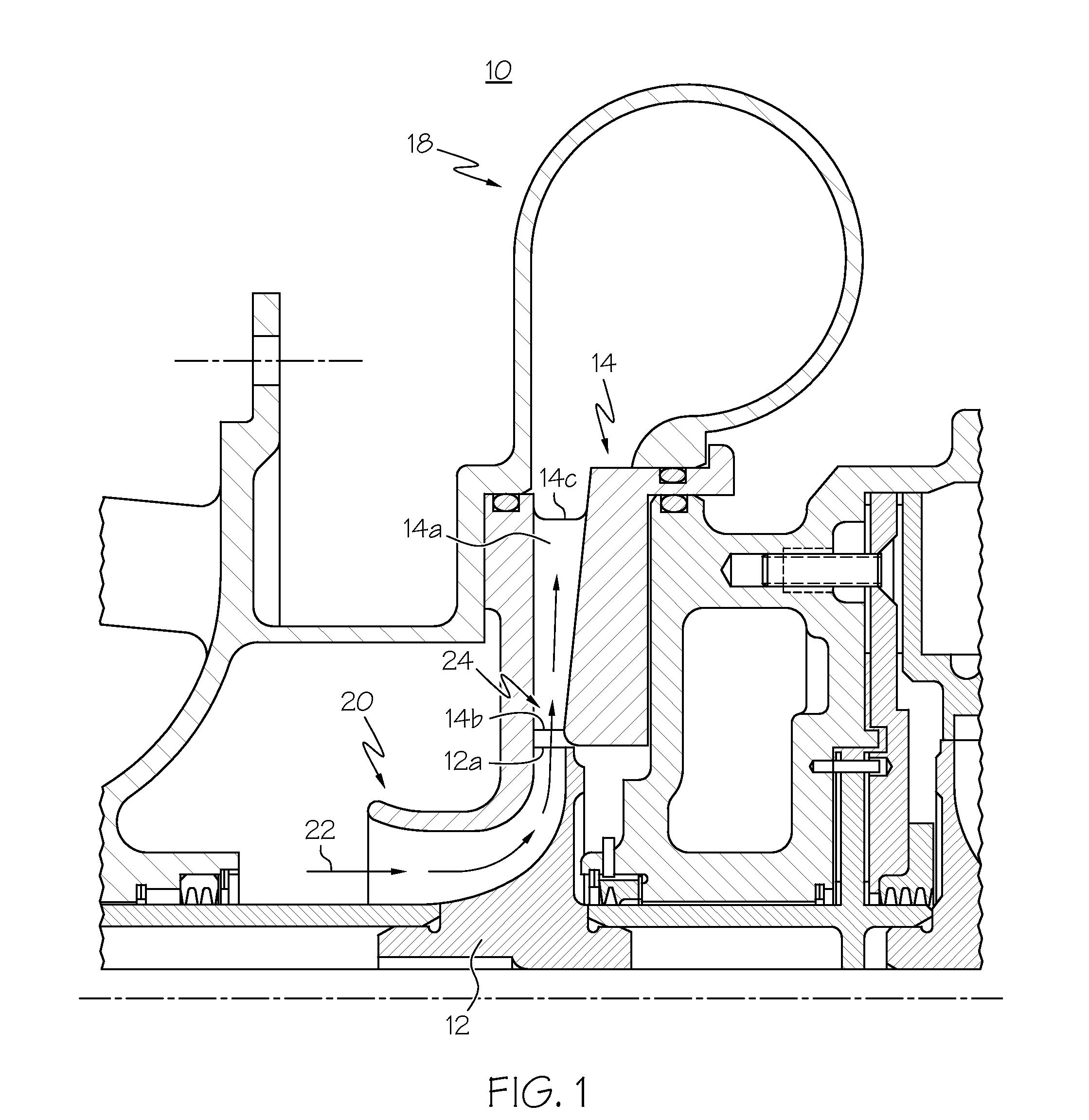
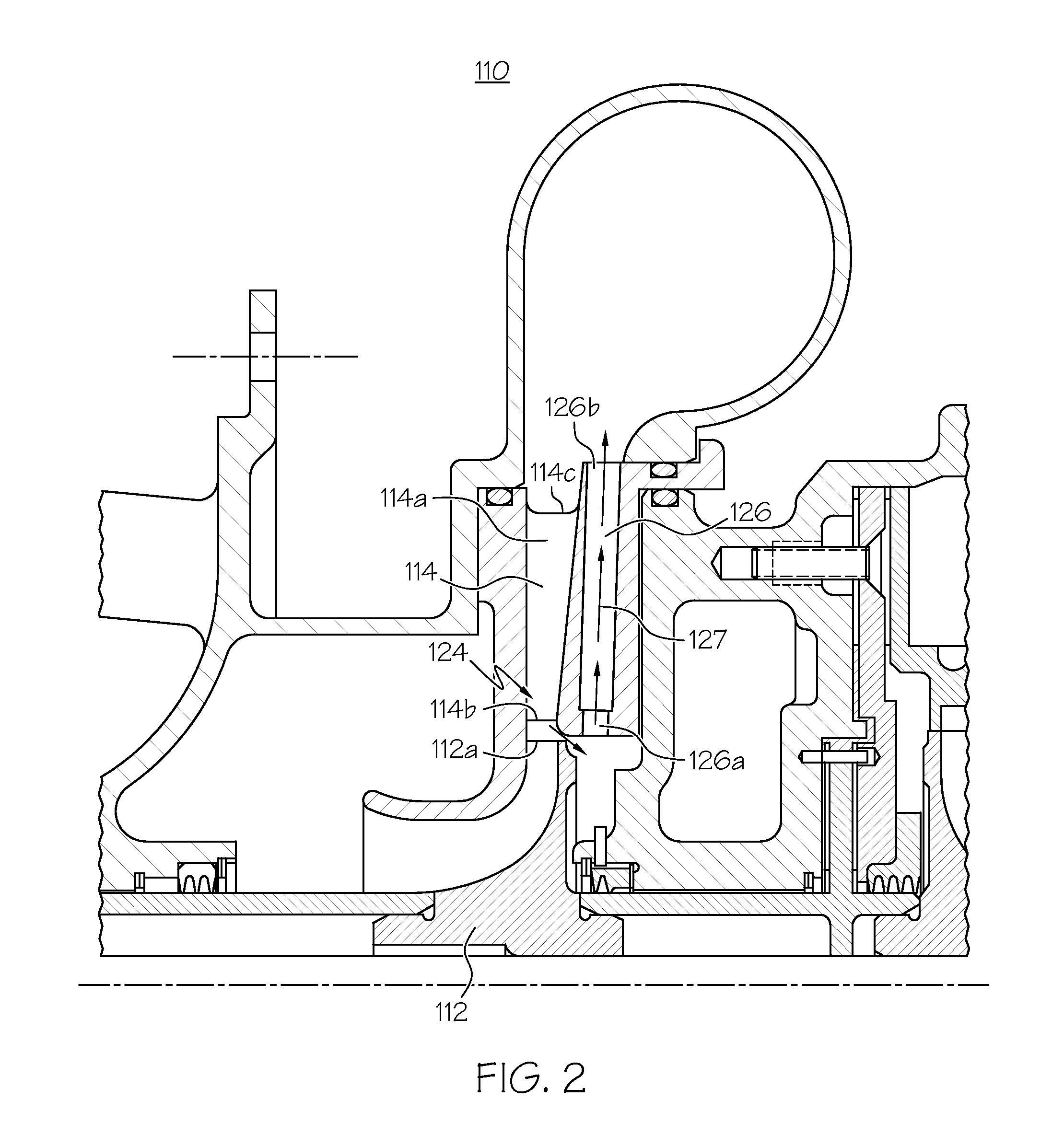
[0023]Broadly, the present invention may be useful in widening a flow range of a centrifugal compressor without affecting its performance characteristics during its most frequent normal operating conditions. More particularly, the present invention may provide a simple expedient that can be applied to a compressor of a particular design to widen the flow range of that compressor.

[0024]In contrast to prior art compressors, among other things, the present invention may provide a bypass in a compressor which may allow a portion of a flow of gas through the compressor to bypass a point in the compressor at which choke and surge conditions develop.

[0025]The ...


PUM


Abstract

A centrifugal compressor is modified by forming a bypass between the leading edge of the compressor diffuser and a point downstream from the throat of the diffuser. The bypass may be unidirectional or bi-directional. In a bi-directional embodiment, an operable flow range of the compressor can be widened in both directions of a compressor map, i.e., extending both the surge and choke margins of a compressor at the expense of normal operating efficiencies. In a unidirectional bypass embodiment the flow range may be increased only in one direction, but there is no diminishment of efficiency of the compressor at normal operating conditions. The modification provides a simple expedient for increasing flow range without a need to redesign a compressor.

Description

BACKGROUND OF THE INVENTION[0001]The present invention is in the field of turbomachinery and, more particularly, centrifugal compressors.[0002]In the field of turbomachinery, some compressor applications such as automotive turbochargers and aircraft air conditioning systems require wide stable operating flow range. Flow range in centrifugal compressors is bounded by surge conditions and choke conditions. Surge conditions develop when volume flow is too low and a discharge process is interrupted. Under surge conditions undesirable cyclical flow instability develops. Choke conditions develop when gas flow at some point in the compressor reaches sonic velocity. Under choke conditions, decreasing compressor outlet pressure does not produce increased mass flow for a given speed and inlet conditions. Thus, mass flow through a compressor is bounded by a minimum associated with surge conditions and a maximum associated with choke conditions.[0003]Many interrelated design parameters may be u...

Claims


Application Information

Patent Timeline
Patent Type & Authority Applications(United States)
IPC IPC(8): F04D29/44F04D17/00
CPCF04D27/0215F04D29/681F04D29/444F04D29/441F05D2250/52
Inventor JOCO, FIDEL M.LIN, FRANK F.ELPERN, DAVE
Owner HONEYWELL INT INC
Why Eureka
Eureka Blog
Learn More