
Helical Gear Supporting Structure, Speed Increaser for Wind Power Generator, and Vertical Shaft Supporting Structure

a technology of wind power generator and supporting structure, which is applied in the direction of gearing details, machines/engines, gearing, etc., can solve the problems of short life of high-loading rows, surface damage and abrasion, and too much room for the lightly-loaded side, etc., to achieve long lifetime and high reliability

Inactive Publication Date: 2008-05-22
NTN CORP
View PDF23 Cites 16 Cited by
  • Summary
  • Abstract
  • Description
  • Claims
  • Application Information

AI Technical Summary

Benefits of technology

[0018]It is an object of the present invention to provide a helical gear supporting structure comprising a double row roller bearing that can appropriately support a gear in accordance with the load status of each row in an environment in which different loads are applied to right and left rows, elongate a substantial lifetime, and be economical without wasting its material, and a speed reducer for a wind power generator comprising such helical gear supporting structure.
[0019]It is another object of the present invention to provide a vertical shaft supporting structure comprising a double row roller bearing that can appropriately support a gear in accordance with the load status of each row in an environment in which different loads are applied to right and left rows, elongate a substantial lifetime, and be economical without wasting its material.

Problems solved by technology

Therefore, the rolling fatigue lifetime of the highly loaded row becomes short.
Meanwhile, sliding is generated between the roller and the track surfaces of the inner and outer rings in the lightly loaded row, which causes surface damage and abrasion.
Although it is considered that the bearing size is increased in order to correspond to a large load, there is too much room for the lightly loaded side, which is not economical.
However, since the axial load is not uniformly applied to the right and left rows of the double row roller bearing, the rolling fatigue lifetime in the row on the highly loaded side becomes short.
Meanwhile, sliding is generated between the roller and the track surfaces of the inner and outer rings in the row on the lightly loaded side, causing surface damage or abrasion.
Although it is considered to increase the bearing size in order to correspond to the large load, there is too much room on the lightly loaded side, which is not economical.

Method used


Image

  • Helical Gear Supporting Structure, Speed Increaser for Wind Power Generator, and Vertical Shaft Supporting Structure
  • Helical Gear Supporting Structure, Speed Increaser for Wind Power Generator, and Vertical Shaft Supporting Structure
  • Helical Gear Supporting Structure, Speed Increaser for Wind Power Generator, and Vertical Shaft Supporting Structure

Examples


Embodiment Construction

[0054]With reference to FIG. 4, a description will be made of a double row roller bearing used in a helical gear supporting structure and a vertical shaft supporting structure according to the present invention such as a speed increaser 1 for a wind power generator shown in FIG. 1 and a swing speed reducer 101 shown in FIG. 3.

[0055]The double row roller bearing shown in FIG. 4 is a double row self-aligning roller bearing 11 comprising an inner ring 12, an outer ring 13, spherical rollers 14 and 15 arranged in double rows between the inner ring 12 and the outer ring 13, and a retainer 16 for retaining the spherical rollers 14 and 15.

[0056]The inner ring 12 has a track surface along the outer diameter surfaces of the spherical rollers 14 and 15, and a middle flange 17, and the outer ring 13 has a track surface common to the spherical rollers 14 and 15 along them. Regarding the roller lengths L1 and L2 of the spherical rollers 14 and 15, the length L2 of the spherical roller 15 is set ...


PUM


Abstract

In a support structure supporting a shaft of a helical gear, a shaft of a speed increase for a wind power generator with a helical gear, or a vertical shaft by a double row rolling element, the double row rolling bearing is so formed that load capacities on the bearing in the right and left rows are different from each other so that the load capacity on the bearing in the row where the rolling bearing receives a large axial load can be increased.

Description

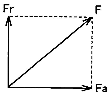
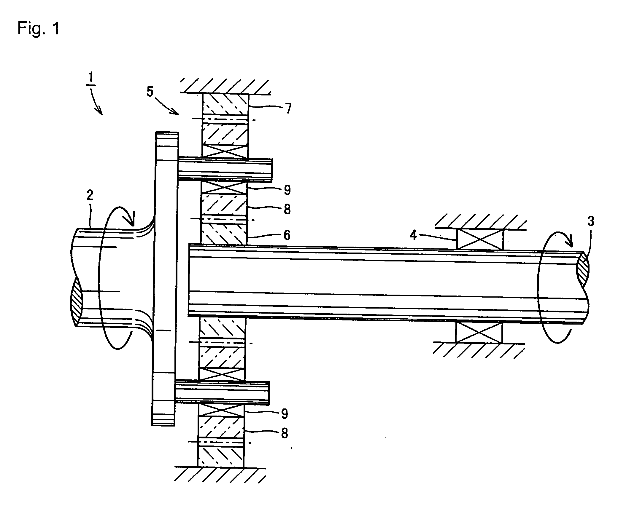
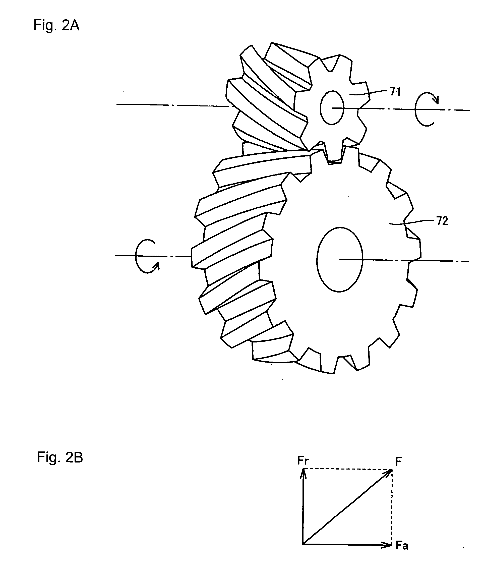
TECHNICAL FIELD[0001]The present invention relates to a helical gear supporting structure, a speed increaser for a wind power generator comprising a helical gear, a vertical shaft supporting structure, and a swing speed reducer comprising a vertical shaft.BACKGROUND ART[0002]Regarding a speed increaser for a wind power generator, Japanese Unexamined Patent Publication No. 2000-337246 discloses a speed increaser for a wind power generator comprising a planet gear mechanism, for example. According to this document, a speed increaser 1 for a wind power generator comprises an input shaft 2 rotating together with a blade receiving wind power, an output shaft 3 supported by a double row roller bearing 4 and connected to a generator, and a planet gear mechanism 5 increasing the rotation speed of the input shaft 2 and transferring it to the output shaft 3 as shown in FIG. 1.[0003]The planet gear mechanism 5 comprises a sun gear 6 connected to the output shaft 3, an internal gear 7 fixed to ...

Claims


Application Information

Patent Timeline
IPC IPC(8): F01B25/06F03D11/02F16H1/08F16H1/28F16H57/021
CPCF03D11/0008F03D11/02F16C19/386F16C19/50F16C19/505F16C23/086F16C2240/34F16H1/28F16H37/041F16H57/021Y02E10/722F16C19/542F16H1/08F16C2361/61F16H1/20F03D80/70F03D15/00F16C19/364F16C19/56F16C2360/31F16C33/36F16C19/38F16C2240/40Y02E10/72F03D15/10
Inventor MATSUMORI, NAOKIHATTORI, JUNICHI
Owner NTN CORP
Learn More