Cooling of turbine blade suction tip rail

a turbine blade and suction tip technology, applied in the field of turbine blade cooling, can solve the problems of high heat load on the blade tip section, life limiting elements, and rubbing between them

Inactive Publication Date: 2008-05-22
SIEMENS ENERGY INC
View PDF10 Cites 44 Cited by
  • Summary
  • Abstract
  • Description
  • Claims
  • Application Information

AI Technical Summary

Problems solved by technology

However, differential thermal elongation and dynamic forces between the blade tip section and outer air seal can cause rubbing therebetween.
Specifically, a high leakage flow will induce a high heat load to the blade tip section, such that gas leakage across the blade tip section and cooling of the blade tip section have to be addressed as a single problem.
The squealer tip section, including the squealer tip rail,

Method used


Image

  • Cooling of turbine blade suction tip rail
  • Cooling of turbine blade suction tip rail
  • Cooling of turbine blade suction tip rail

Examples


Embodiment Construction

[0013]In the following detailed description of the preferred embodiment, reference is made to the accompanying drawings that form a part hereof, and in which is shown by way of illustration, and not by way of limitation, a specific preferred embodiment in which the invention may be practiced. It is to be understood that other embodiments may be utilized and that changes may be made without departing from the spirit and scope of the present invention.

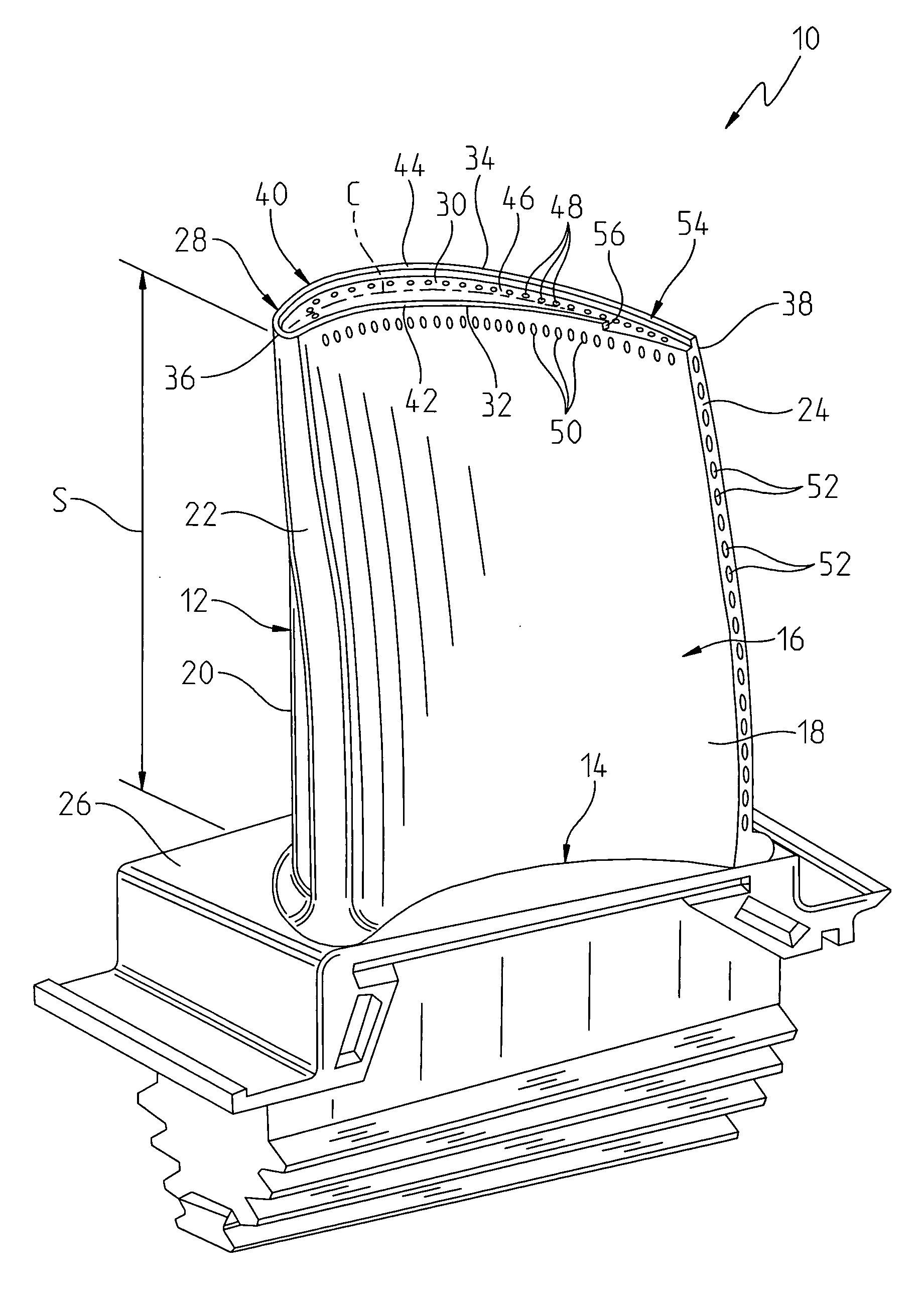
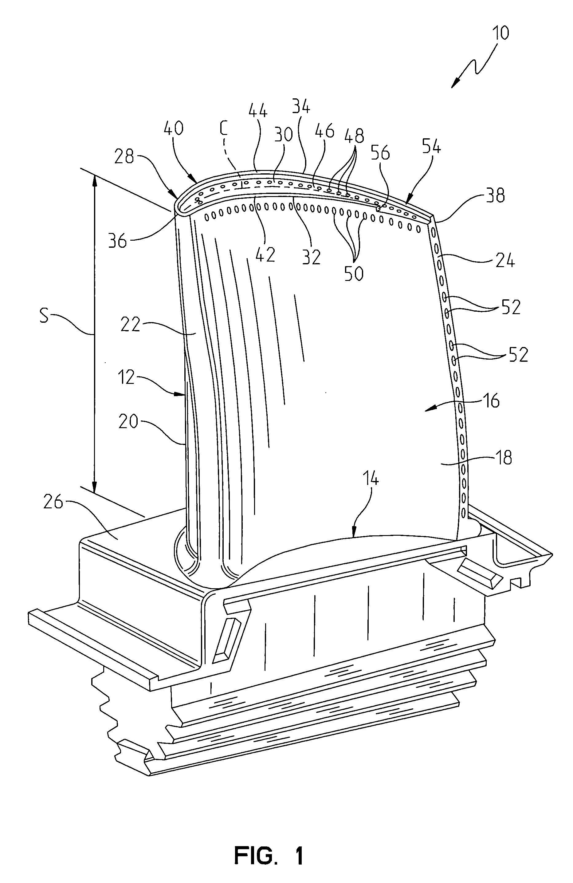
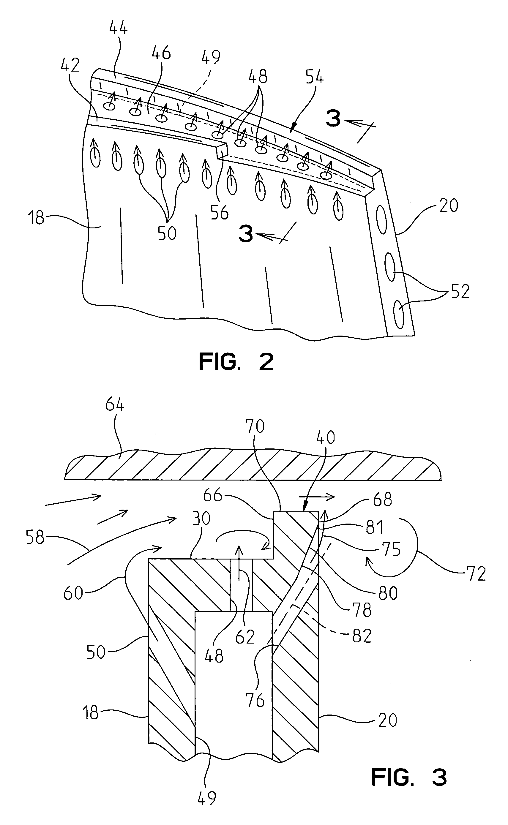
[0014]The present invention provides a construction for the blade tip section of a rotating blade for a combustion gas turbine, where the blade tip section includes a squealer tip rail that is configured to provide a reduction in the vena contractor associated with secondary leakage flow passing the blade tip section. The geometry of the squealer tip rail operates in combination with an injected cooling flow to reduce blade leakage flow and heat load.

[0015]Referring to FIG. 1, an exemplary turbine blade 10 for a gas turbine engine is ill...


PUM


Abstract

A turbine blade including an airfoil, the airfoil including an airfoil outer wall having pressure and suction sidewalls joined together at chordally spaced apart leading and trailing edges extending radially outwardly from a blade root to a blade tip surface. A continuous squealer tip rail extends radially outwardly from and substantially continuously around the blade tip surface forming a radially outwardly open squealer pocket. The squealer tip rail includes an aft portion adjacent to the trailing edge, where the pressure side tip rail is discontinued in the chordal location of the aft portion. A plurality of chordally spaced film cooling holes are provided in a surface of the suction sidewall and provides a cooling fluid flow along the aft portion of the squealer tip rail surface to define a sub-boundary layer or film of cooling fluid between a hot gas vortex flow and the aft portion of the squealer tip rail at the suction sidewall.

Description

FIELD OF THE INVENTION[0001]The present invention relates generally to turbine blades and, more particularly, to cooling of a surface of a turbine blade.BACKGROUND OF THE INVENTION[0002]In a turbomachine, such as a gas turbine engine, air is pressurized in a compressor then mixed with fuel and burned in a combustor to generate hot combustion gases. The hot combustion gases are expanded within the turbine section where energy is extracted to power the compressor and to produce useful work, such as powering a propeller for an aircraft in flight or turning a generator to produce electricity. The hot combustion gas travels through a series of turbine stages. A turbine stage may include a row of stationary vanes followed by a row of rotating turbine blades, where the turbine blades extract energy from the hot combustion gas for powering the compressor and providing output power. Since the turbine blades are directly exposed to the hot combustion gas, they are typically provided with inte...

Claims


Application Information

Patent Timeline
IPC IPC(8): F01D5/18
CPCF01D5/186F01D5/20F05D2260/202Y02T50/676F05D2240/55F01D11/08Y02T50/60
Inventor LIANG, GEORGEMATHEWS, RALPH WARREN
Owner SIEMENS ENERGY INC
Why Eureka
Try Eureka