Antenna device, wireless cellular network and method of capacity expansion

a wireless cellular network and antenna device technology, applied in the field of mobile communication technologies, can solve the problems of increased costs, reduced capacity density of each base station, and limited capacity of each base station, and achieve the effect of high costs

Active Publication Date: 2008-05-22
HUAWEI TECH CO LTD
View PDF8 Cites 6 Cited by
  • Summary
  • Abstract
  • Description
  • Claims
  • Application Information

AI Technical Summary

Benefits of technology

[0013] 4. The existing solution just evades the problem of capacity expansion temporarily. The capacity will be saturated after years, so that the problem of capacity expansion with high costs will be inevitable.

Problems solved by technology

However, the capacity of each base station is limited, so its capacity density will be decreased with an enlarged coverage area.
However, capacity expansion by means of network splitting requires additional necessary equipment, results in extra costs, and requires complex reconfiguration of local networks.
Consequently, the network capacity expansion is neither “smooth” nor cost effective.
Accordingly, the low initial investment conflicts with the high capacity expansion cost.
However, for a wireless communication system, especially a 3G wireless communication system in compliance with WCDMA and CDMA2000 standards, capacity expansion by means of establishing new base stations requires addition of necessary equipment, and also causes extra cost.
For instance, a new base station needs an additional site which gives rise to site costs.
Moreover, because the coverage in a 3G system relates to capacity, both network planning and engineering are complex.
Therefore, adding a new base station requires network planning that should consider both the new base station to be established and existing base stations around it, which results in new problems.
Accordingly, for an addition of a new base station, there may be a “jump” with respect to costs, technologies and engineering, and consequently, such capacity expansion is not smooth.
Furthermore, because the coverage areas are not normative, it may be difficult to obtain a good coverage for some dead zones regardless of adjusting.
An advantage of this approach is that it satisfies a requirement for the number base stations in the coming years, while its disadvantage is that the initial investment will be large, which may bring an investment challenge to an operator.
Moreover, the total number of base stations fails to be reduced, and the total cost of base station sites can not be lowered.
Large initial investment: the “One-off” planning is to ensure that the network capacity will be sufficient in the coming years without any capacity expansion, and this means that more cellular networks shall be established at one time, which results in large initial investment and increased financial cost and risk;
High costs for base station sites: each base station involves some fixed costs such as cost of site building, accumulators, and tenancy.
The more the base station sites, the higher the costs.
Because the “one-off” planning requires more base stations, the costs of base station sites are higher.
Difficulty in planing: the “one-off” planning requires more base stations, but sometimes there is no appropriate site available for a base station at a place intended for the base station, which renders the network planning difficulty.
The capacity will be saturated after years, so that the problem of capacity expansion with high costs will be inevitable.

Method used


Image

  • Antenna device, wireless cellular network and method of capacity expansion
  • Antenna device, wireless cellular network and method of capacity expansion
  • Antenna device, wireless cellular network and method of capacity expansion

Examples


first embodiment

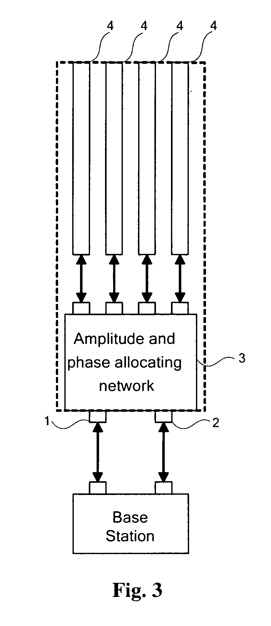
[0037]FIG. 3 is a structural diagram of an antenna device according to the present invention. The antenna device is connected with a base station through a left contact 1 and a right contact 2. The device further includes an amplitude and phase allocating network 3 for allocating signals from the base station to an array of antennas with designed amplitudes and phases, and a splitting antenna 4 with an array of antennas comprising four columns for transmitting and receiving signals. Signals output from the left contact 1 or the right contact 2 pass the amplitude and phase allocating network 3 to generate four outputs respectively linked with the antennas of the array 4.

[0038] Specifically, a structure of the amplitude and phase allocating network 3 is illustrated in FIG. 4. The amplitude and phase allocating network 3 includes:

[0039] two layer-1 3-decibel 90-degree bridges 51 and 52, each of which halves signals from one input channel to two channels and outputs, signals from the t...

second embodiment

[0060] the allocation of amplitudes and phases by the amplitude and phase allocating network particularly includes the following steps:

[0061] base station signals from the left contact 1 enter the 7.7-decibel coupler 111, power of one output of the coupler is lower than that of the another output of the coupler by 7.7 decibels; one of the outputs of the 7.7-decibel coupler 111 enters the 3-decibel 90-degree bridge 131 and is powered-halved to generate two outputs, one of which lags the other by a phase of 90 degrees, the one of the two outputs enters an antenna array a, and the other of the outputs enters an antenna array d; the other of the outputs of the 7.7-decibel coupler 111 passes the 180-degree phase shifter 121 and is phase delayed by 180 degrees, then enters the 3-decibel 90-degree bridge 132, where it is power-halved to generate two outputs, one of which lags the other by a phase of 90 degrees, the one of the two outputs enters an antenna array c, and the other of the two...


PUM


Abstract

An antenna device, a wireless cellular network, and a method of capacity expansion are provided. The antenna device includes: a contact element adapted to connect a base station to receive input signals from the base station; an amplitude and phase allocating element adapted to allocate the input signals received by the contact element according to designed amplitudes and phases; an antenna element comprising an array of antennas comprising an even number of columns, and adapted to receive and transmit the input signals allocated with the amplitudes and phases. An array of antennas comprising an even number of columns has been adopted, and a feed network construction of the antenna system has been improved, so that through adjusting amplitudes and phases of original signals from a base station, a smooth capacity expansion of the network can be achieved without adjusting antenna directivities, thus reducing the workload and complexity for capacity expansion.

Description

[0001] This application claims priorities from Chinese Patent Applications No. 200610074488.8, filed on Apr. 21, 2006, titled “WIRELESS CELLULAR NETWORK AND WIRELESS CELLULAR NETWORK EXPANSION REALIZING METHOD”, and No. 200610087159.7, filed on Jun. 15, 2006, titled “ANTENNA DEVICE FOR BASE STATION AND METHOD FOR ANTENNA DEVICE OF BASE STATION”, contents of which are incorporated herein by reference in its entirety. FIELD OF THE INVENTION [0002] The present invention relates to mobile communication technologies and in particular to an antenna device, a wireless cellular network and a method for expanding capacity of a wireless cellular network. BACKGROUND OF THE INVENTION [0003] In a mobile communication system, a service area is covered by a plurality of Base Stations (BTS). An existing antenna of a base station has a single column of antennas, where there is only a longitudinal feed network but no horizontal feed network with a directivity diagram of approximately a regular hexago...

Claims


Application Information

Patent Timeline
Patent Type & Authority Applications(United States)
IPC IPC(8): H04B1/18H04W16/00
CPCH01Q1/246H04W16/00H01Q25/00H01Q3/40
Inventor LL, YARUIAL, MINGZHAO, TIANZHONGJIANG, JINDI
Owner HUAWEI TECH CO LTD
Why Eureka
Try Eureka