Heart valve chord cutter

a heart valve and chord cutting technology, applied in the field of heart related diseases, can solve the problems of heart damage, patients to a tremendous amount of pain and discomfort, and require long recovery and/or hospitalization periods

Inactive Publication Date: 2008-05-22
COX DANIEL L
View PDF6 Cites 16 Cited by
  • Summary
  • Abstract
  • Description
  • Claims
  • Application Information

AI Technical Summary

Problems solved by technology

This may lead to heart damage over a period of time.
These invasive procedures subject patients to a tremendous amount of pain and discomfort and require lengthy recovery and / or hospitalization periods.
Patients with congestive heart failure may not be able to tolerate the surgical procedures, leaving them with little or no alternative to treat their defective heart valves.
Moreover, reducing the annular size alone may still leave the patient with regurgitation symptoms because the mitral valve leaflet may still be tethered by chordae to the displaced papillary muscles and ventricular walls.

Method used


Image

  • Heart valve chord cutter
  • Heart valve chord cutter
  • Heart valve chord cutter

Examples


Embodiment Construction

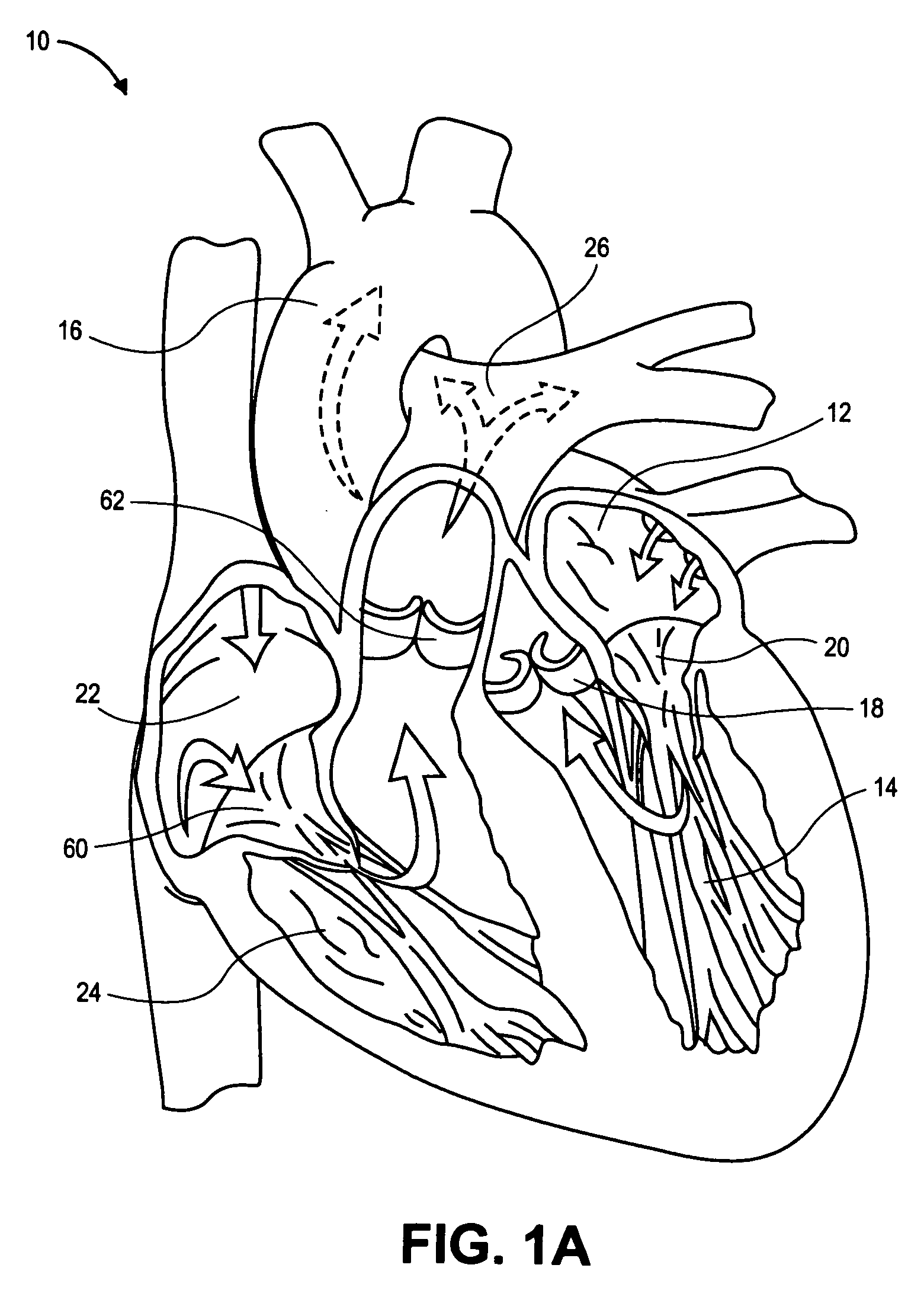
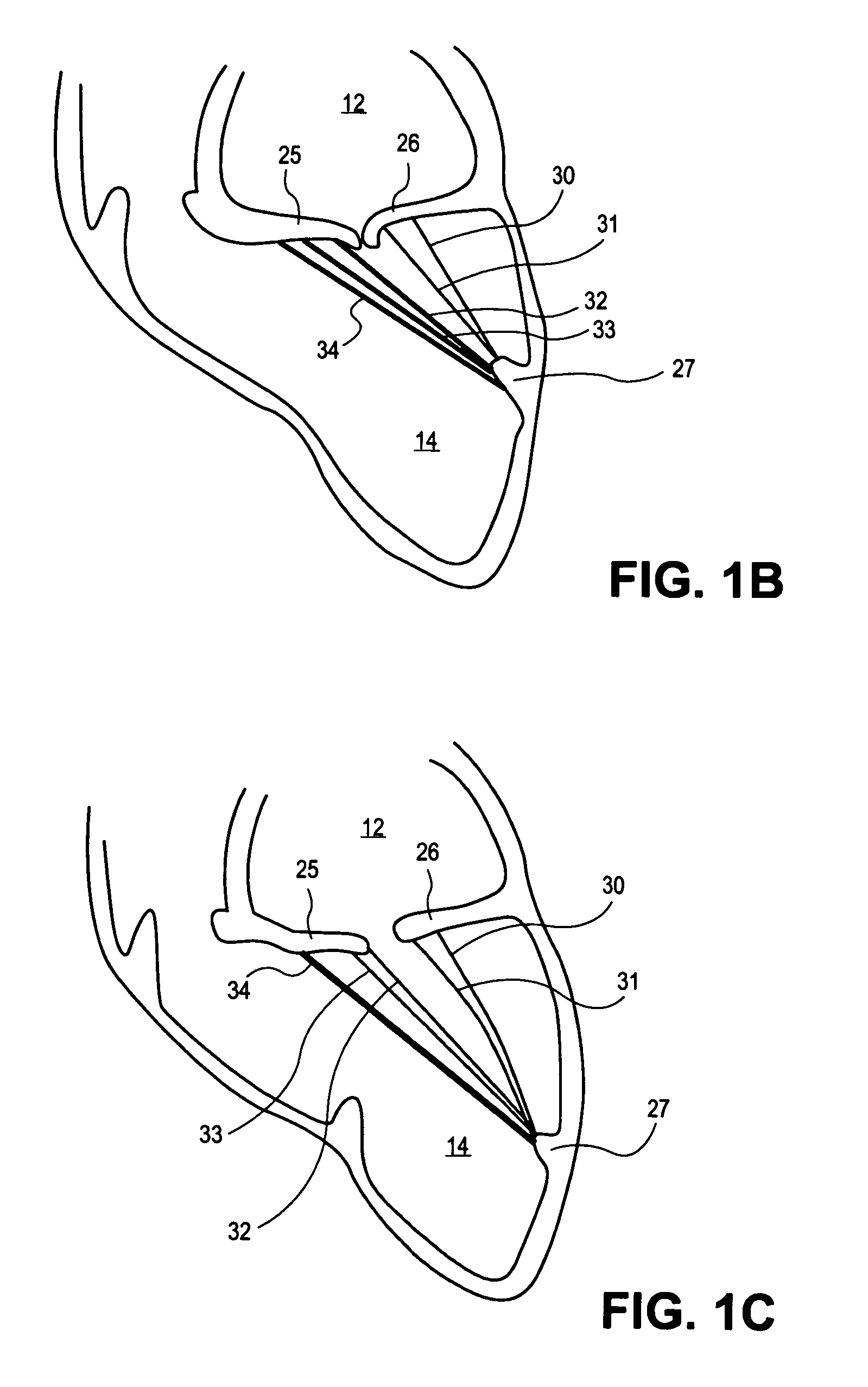
[0029] In the following description, numerous specific details are set forth such as examples of specific materials or components in order to provide a thorough understanding of the present disclosure. It will be apparent, however, to one skilled in the art that these specific details need not be employed to practice the disclosure. In other instances, well known components or methods have not been described in detail in order to avoid unnecessarily obscuring the present disclosure. Embodiments of a medical device discussed below are described with respect to the treatment of a mitral valve. It may be appreciated, however, that other heart valves or body tissue may be treated, and embodiments of the medical device are not limited in their applicability to treating the mitral valve.

[0030] Embodiments of a medical device and methods for treating the mitral valve percutaneously are described. A medical device, in one embodiment, may be used to treat mitral valve regurgitation or prola...


PUM


Abstract

A medical device and method for percutaneously treating a heart valve. In one embodiment, the medical device includes a catheter having a proximal portion, a distal portion, and a notch formed near the distal portion. A cutting element may be disposed within the distal portion and is moveable across the notch to slice through a heart chord.

Description

[0001] The present application is a divisional of co-pending U.S. application Ser. No. 10 / 295,383, filed Nov. 15, 2002.TECHNICAL FIELD [0002] The disclosure, in one embodiment, relates generally to the treatment of heart related diseases, and more particularly, in one embodiment, to the treatment of defective heart valves. BACKGROUND [0003]FIG. 1A illustrates a heart 10 with a partial internal view and arrows indicating the direction of blood flow within the heart. Four valves in the heart 10 direct the flow of blood within the left and right sides of the heart. The four valves include a mitral valve 20, an aortic valve 18, a tricuspid valve 60, and a pulmonary valve 62 as illustrated in FIG. 1A. The mitral valve 20 is located between the left atrium 12 and the left ventricle 14. The aortic valve 18 is located between the left ventricle 14 and the aorta 16. These two valves direct oxygenated blood coming from the lungs, through the left side of the heart, into the aorta 16 for distr...

Claims


Application Information

Patent Timeline
Patent Type & Authority Applications(United States)
IPC IPC(8): A61B17/32
CPCA61B17/320016A61B17/32075A61B2017/32004A61B2017/00243A61B2017/003A61B17/320783
Inventor COX, DANIEL L.
Owner COX DANIEL L
Why Eureka
Try Eureka