Backup structure for an uprising pipe or downfalling pipe in a vacuum degassing apparatus

a vacuum degassing and back-up structure technology, which is applied in liquid degasification, separation processes, manufacturing tools, etc., can solve the problems of vacuum degassing vessel breaking, glass production cost increase, and elongation, so as to improve glass production and reduce glass production cost

Inactive Publication Date: 2008-05-29
ASAHI GLASS CO LTD
View PDF4 Cites 14 Cited by
  • Summary
  • Abstract
  • Description
  • Claims
  • Application Information

AI Technical Summary

Benefits of technology

[0014]It is an object of the present invention to provide a backup structure for an uprising pipe or downfalling pipe in a vacuum degassing apparatus, which is capable of avoiding a case where the elongation of refractory bricks caused by thermal expansion breaks or deforms a structure for relieving the elongation of the refractory bricks, a vacuum degassing apparatus using the backup structure, and a method for depressurizing and degassing molten glass by using the vacuum degassing apparatus.
[0021]In accordance with the backup structure of the present invention, when refractory bricks, which are disposed around the uprising pipe or the downfalling pipe of the vacuum degassing apparatus, are thermally expanded, it is possible to prevent the thermal expansion relief member from being broken or deformed by the elongation of the refractory bricks.
[0023]The vacuum degassing apparatus according to the present invention cause no problems of breaking or deforming the thermal expansion relief member during heating-up or operation, and widening the joint between adjacent refractory bricks because of using the backup structure according to the present invention as the backup for the uprising pipe or the downfalling pipe. The vacuum degassing apparatus according to the present invention can be used for a long term without exchanging, e.g., the thermal expansion relief member or refractory bricks for a new one. Accordingly, the vacuum degassing apparatus according to the present invention can be used to improve the productivity of glass and to reduce the production cost of glass.

Problems solved by technology

The inventors have found that the backup structure disclosed by Patent Document 1 may have a problem of elongation caused by the thermal expansion of insulating bricks disposed around the uprising pipe and the downfalling pipe thereof.
If the insulating bricks are elongated to reach the vacuum degassing vessel disposed above the pressing plate, it is likely that the vacuum degassing vessel is broken.
However, fused cast refractories have a higher thermal expansion rate than insulating refractory bricks and general refractory bricks.
In addition, since fused cast refractories are excellent in mechanical strength, such as compressive strength, it is likely that the pressing plate is broken when the elongation of the fused cast refractories is applied to the pressing plate.

Method used


Image

  • Backup structure for an uprising pipe or downfalling pipe in a vacuum degassing apparatus
  • Backup structure for an uprising pipe or downfalling pipe in a vacuum degassing apparatus
  • Backup structure for an uprising pipe or downfalling pipe in a vacuum degassing apparatus

Examples


example

[0089]Now, the present invention will be described more specifically based on an example. It should be noted that the present invention is not limited to the example.

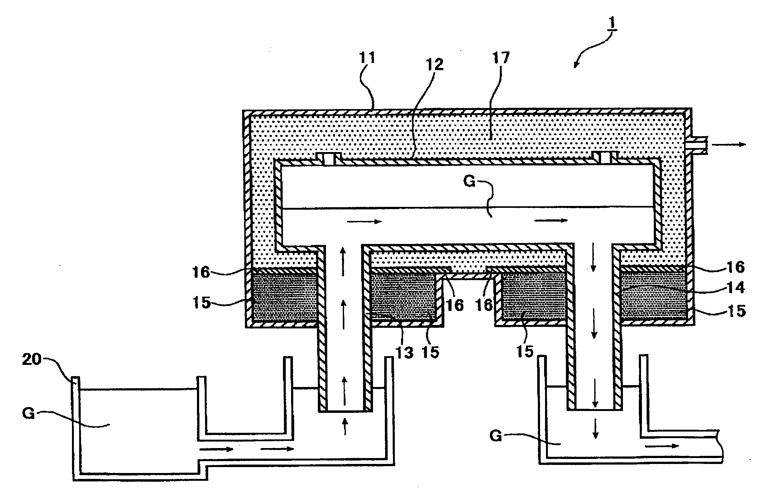
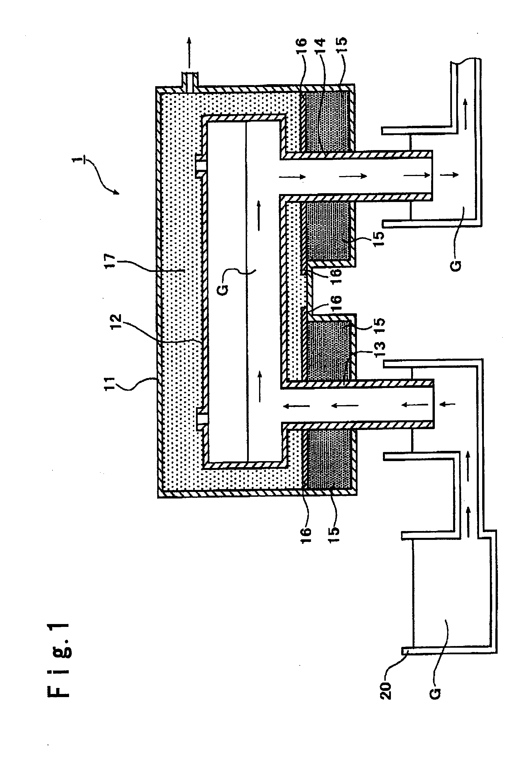
[0090]In the example, the vacuum degassing apparatus 1 shown in FIG. 1 was used to vacuum-degas molten glass. The backup structure for each of the uprising pipe 13 and the downfalling pipe 14 in the vacuum degassing apparatus 1 comprised the backup structure shown in FIG. 2.

[0091]The dimensions and the material of each element of the vacuum degassing apparatus 1 were as follows:

[0092]Vacuum housing 11: Made of stainless steel

[0093]Vacuum degassing vessel 12: Made of a platinum / rhodium alloy (90 mass % of platinum and 10 mass % of rhodium)

[0094]Dimensions of degassing vessel

[0095]Length: 2 m

[0096]Inner diameter: 120 mm

[0097]Thickness: 1 mm

[0098]Uprising pipe 13 and downfalling pipe 14: Made of a platinum / rhodium alloy (90 mass % of platinum and 10 mass % of rhodium)

[0099]Dimensions of each of uprising pipe and downfallin...


PUM

PropertyMeasurementUnit
creep strengthaaaaaaaaaa
compressive strengthaaaaaaaaaa
thicknessaaaaaaaaaa

Abstract

A backup structure for an uprising pipe or a downfalling pipe of a vacuum degassing apparatus including the uprising pipe, a vacuum degassing vessel and the downfalling pipe, comprises the uprising pipe or the downfalling being made of platinum or a platinum alloy and having refractory bricks disposed therearound; and the refractory bricks having a thermal expansion relief member disposed on a top end thereof, the thermal expansion relief member comprising a material selected from a metal material and a ceramic material having a creep strength (JIS Z2271: 1993) of 35 MPa or above at 760° C.

Description

BACKGROUND OF THE INVENTION[0001]1. Field of the Invention[0002]The present invention relates to a backup structure for an uprising pipe or downfalling pipe in a vacuum degassing apparatus, more specifically a backup structure for an uprising pipe or downfalling pipe made of platinum or a platinum alloy in a vacuum degassing apparatus. The present invention also relates to a vacuum degassing apparatus and a vacuum degassing method using the above-mentioned backup structure as the backup structure for an uprising pipe or downfalling pipe.[0003]2. Description of the Related Art[0004]FIG. 3 is a cross-sectional view showing a general structure of vacuum degassing apparatuses. The vacuum degassing apparatus 100 shown in FIG. 3 is used to depressurize and degas molten glass G in a melting tank 200 and continuously feed the degassed molten glass to a subsequent treatment bath. The vacuum degassing apparatus 100 shown in FIG. 3 includes a vacuum degassing vessel 102 formed in a cylindrical...

Claims


Application Information

Patent Timeline
Patent Type & Authority Applications(United States)
IPC IPC(8): C03B5/16
CPCB01D19/0031C03B5/43C03B5/2252B01D19/0042Y02P40/57B01D19/00C03B5/225
Inventor TAKESHITA, SHINJIISHIMURA, KAZUHIKONAGNO, SEI
Owner ASAHI GLASS CO LTD
Why Eureka
Try Eureka