Externally Mounted Vortex Generators for Flow Duct Passage

a vortex generator and flow duct technology, applied in the direction of liquid fuel engines, combustion air/fuel air treatment, lighting and heating apparatus, etc., can solve the problems of reducing affecting the efficiency and the direction of the flow control system cannot be properly chosen, so as to reduce the drag a little, and the structural stability is less.

Inactive Publication Date: 2008-05-29
NORRIS THOMAS R
View PDF15 Cites 49 Cited by
  • Summary
  • Abstract
  • Description
  • Claims
  • Application Information

AI Technical Summary

Benefits of technology

[0044]In a turbomachine with a high speed gas flow section having a strong adverse pressure gradient with high speed free stream gas flow over a primary aerodynamic surface for confining the high speed gas flow, a high drag vortex generator for inhibiting the formation of boundary layer gas flow is mounted. The high drag vortex generator includes a mounting for supporting the high drag vortex generator at a spatial interval in the high speed gas flow above the primary aerodynamic surface confining duct flow. The high drag vortex generator is supported from the mounting and extends from the mount in the high speed gas flow equal to or less than the full distance to the primary aerodynamic surface confining diffuser flow. Each high drag vortex generator includes first vanes and second vanes, in which either the first and second vanes can be the mount. The first vanes have first flow confining components and the second vanes have second flow confining components at substantial right angles with respect to the first flow confining components of the first vanes. The first vane flow confining components deflect fluid flow from the free stream gas flow towards and / or away from the primary aerodynamic surface. The flow confining components of the second vane maintain the deflected fluid flow along a path towards and / or away from the primary aerodynamic surface. The second vanes flow confining components prevent the excessive sideways deflection parallel to the primary aerodynamic surface, enabling penetration through undeflected free stream gas flow. This enables boundary layer formation downstream from the vortex generator to be inhibited by mixture of the deflected free stream gas flow into the volume adjacent the primary aerodynamic surface where the boundary layers might otherwise thicken excessively or accumulate.
[0048]The high drag vortex generator system diverts portions of the flow and may also assist in changing the average direction of flow. If the entire flow in a duct is diverted, in effect, the high drag vortex generators act in place of turning vanes, but of course, with some portions of flow diverted more than others. Uses of the high drag vortex generator system include increasing or reducing swirl angle, or turning the flow through a bend in a duct, or aiding flow in conforming to curves in a duct wall, such as a change in wall taper angle or radius in an annular duct, or a bend in a rectangular or square exhaust duct. In these cases, the curved elements of the high drag vortex generator will in general approximately trace the intended average curvature of the flow, plus or minus the diversion angles of the individual elements.
[0059]A less preferred series arrangement has only a single spine mounting for the vanes, created by deleting one leg of the “U” shaped elements, and the spine joining the crosses of the “U”'s in their mid-section or ends. This arrangement reduces drag slightly, but is less robust structurally, and the deflected gas will not penetrate as easily either through the high energy free stream gas or into a boundary layer as with the full “U” shaped elements.

Problems solved by technology

This device, having high solidity, severely restricts flow as well as developing an intense swirl necessary for proper burner flame holding and burner function.
However, being of small size and fastened directly to the aerodynamic surface, these vortex generators can become wholly immersed in a thickened boundary layer or stalled flow accumulations, resulting in ineffectiveness.
Specifically, the direction of gas flow is not always possible to ascertain in boundary layers; thus the direction of vane alignment cannot be properly chosen.
I have found that the convoluted downstream edge causes deflection along the circumference of the convoluted downstream edge; it does not cause efficient deflection towards and away from the diffuser walls so as to have an efficient effect on boundary layers downstream of the disclosed diffuser.
This result appears to be counterintuitive and unexpected, given the high drag penalty of the vortex generator itself.
It is well known that diffusers with small included angles between walls, about 6 to 7 degrees, produce the highest effectiveness of all, but are rarely feasible because of their excessive length.
First, wings normally operate with relatively high efficiency aerodynamic surfaces.
This is to be contrasted with turbomachines having diffusing flow passages and their sometimes the thick boundary layers and potentially unstable accumulations of boundary layers gases, in which direction of flow can be more than 45 degrees to the direction of free stream flow, often in varying and unpredictable angles.
Fourth, conventional vortex generators usually have the junction of the vanes and mounting, and all or a substantial part of their surface area, within the low velocity boundary layer.
Fifth, conventional vortex generators do not have structure and vanes with multiple or structurally redundant attachments to the flow passage walls or structure.
Most importantly, the vortex generator of my invention is not foreseen as suited to be mounted onto any substantial span of the wing of an aircraft, replacing conventional vortex generators in the usual case, because of high drag, weight, and complexity.

Method used


Image

  • Externally Mounted Vortex Generators for Flow Duct Passage
  • Externally Mounted Vortex Generators for Flow Duct Passage
  • Externally Mounted Vortex Generators for Flow Duct Passage

Examples


Embodiment Construction

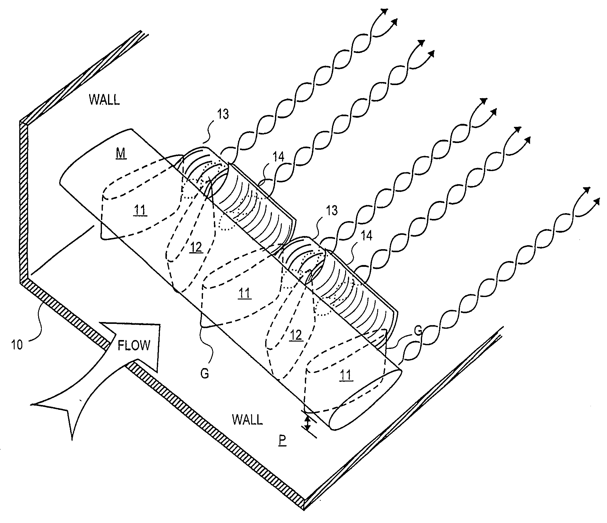
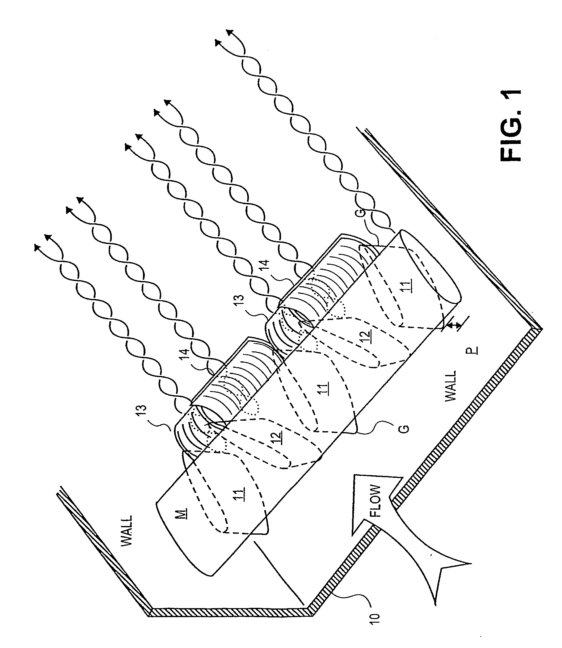
[0081]Referring to FIG. 1, one half of a U-shaped duct 10 constituting the primary aerodynamic surface P is shown. Utilizing this example, the reader will understand that the duct in which the gas flow is confined does not necessarily have to be a closed duct. For example the duct may be a flow diverting duct of U-shape or compressor discharge diffuser placed within the exhaust of a turbo machine.

[0082]A mounting strut M is mounted to one wall of U-shaped duct 10 and is shown extending across U-shaped duct 10. Mounting M is the surface to which vortex generators G are mounted. It is important to understand that mounting M and vortex generators G are in the free stream gas flow. Further, vortex generators G stand from the underside of mounting M and extend to and toward primary aerodynamic surface P. These vortex generators G may never reach the primary aerodynamic surface; instead they may stop short of the primary aerodynamic surface P. In this extension to and toward primary aerod...


PUM


Abstract

A high drag vortex generator for inhibiting the formation of boundary layer gas flow is mounted in a duct having a strong adverse pressure gradient with high speed gas flow over a primary aerodynamic. The vortex generator includes a mounting for supporting the high drag vortex generator at a spatial interval in the high speed gas flow above the primary aerodynamic surface. The high drag vortex generator is supported from the mounting and extends from the mounting in the high speed gas flow less than the full distance to the primary aerodynamic surface. Each high drag vortex generator includes first and second vanes. The first and second vanes have flow confining components at substantial right angles to one another. The vanes flow confining components deflect fluid flow towards and / or away from the primary aerodynamic surface inhibiting boundary layer formation downstream of the vortex generator.

Description

CROSS-REFERENCES TO RELATED APPLICATIONS[0001]This application claims the benefit of US Provisional Patent Application entitled Externally Mounted Vortex Generators with Diffuser Flow Duct Passages filed by Thomas R. Norris as Ser. No. 60 / 560,951 on Apr. 9, 2004.STATEMENT AS TO RIGHTS TO INVENTIONS MADE UNDER FEDERALLY SPONSORED RESEARCH OR DEVELOPMENT[0002]NOT APPLICABLEREFERENCE TO A “SEQUENCE LISTING,” A TABLE, OR A COMPUTER PROGRAM LISTING APPENDIX SUBMITTED ON A COMPACT DISK[0003]NOT APPLICABLE[0004]This invention relates to vortex generators for improving flow over an aerodynamic surface using an improved vortex generator system. More particularly the improved vortex generators improve flow in zones that include unusually strong adverse pressure gradients and / or thick unstable boundary layers.[0005]The disclosed vortex generator set is positioned a short distance away from the aerodynamic surface. At this distance, the vortex generator system is expected to be out of the low e...

Claims


Application Information

Patent Timeline
Patent Type & Authority Applications(United States)
IPC IPC(8): F15D1/02F01D9/02
CPCF01D25/30F02C7/04F05D2260/22141F05D2250/50Y02T50/675Y02T50/60
Inventor NORRIS, THOMAS R.
Owner NORRIS THOMAS R
Why Eureka
Try Eureka