
Joint Between Wood Pieces

a technology of wood pieces and joints, applied in the direction of cables, cables for vehicles/pulleys, structural elements, etc., can solve problems such as inability to meet the needs of us

Inactive Publication Date: 2008-05-29
POUTANEN TUOMO
View PDF23 Cites 6 Cited by
  • Summary
  • Abstract
  • Description
  • Claims
  • Application Information

AI Technical Summary

Benefits of technology

"The invention is a new joint design that solves problems with previous joints, such as being too rigid, difficult to produce, and requiring separate connection pieces. The joint is better in terms of firmness, versatility, and visual appearance. It uses a new cutting method that allows for a shallow depth of cut in the joint, which is important for its firmness. The joint is also easier to assemble and disassemble, and can be connected at various angles. Additionally, the joint is better suited for three-dimensional structures and can be used with finger glue. Overall, the joint design is more efficient and effective in solving these problems."

Problems solved by technology

There can be in the joint small gaps caused by inaccuracy of the cutting tool and restrictions of the form geometry of the cutting grooves.
This is not possible if the diagonals could not be turned and also not connected to the chords in oblique angles.

Method used


Image

  • Joint Between Wood Pieces
  • Joint Between Wood Pieces

Examples


Embodiment Construction

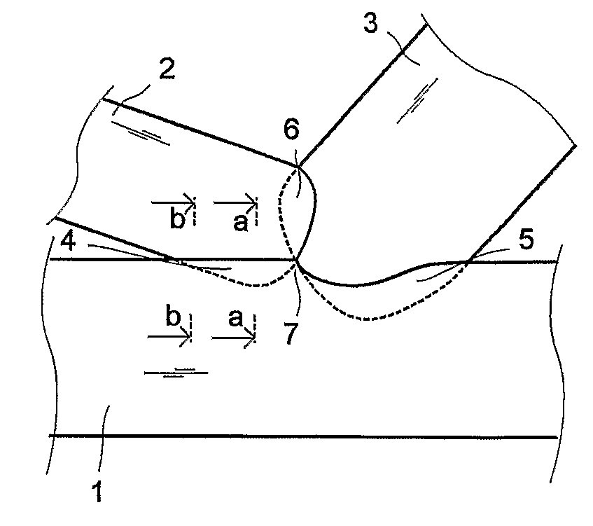
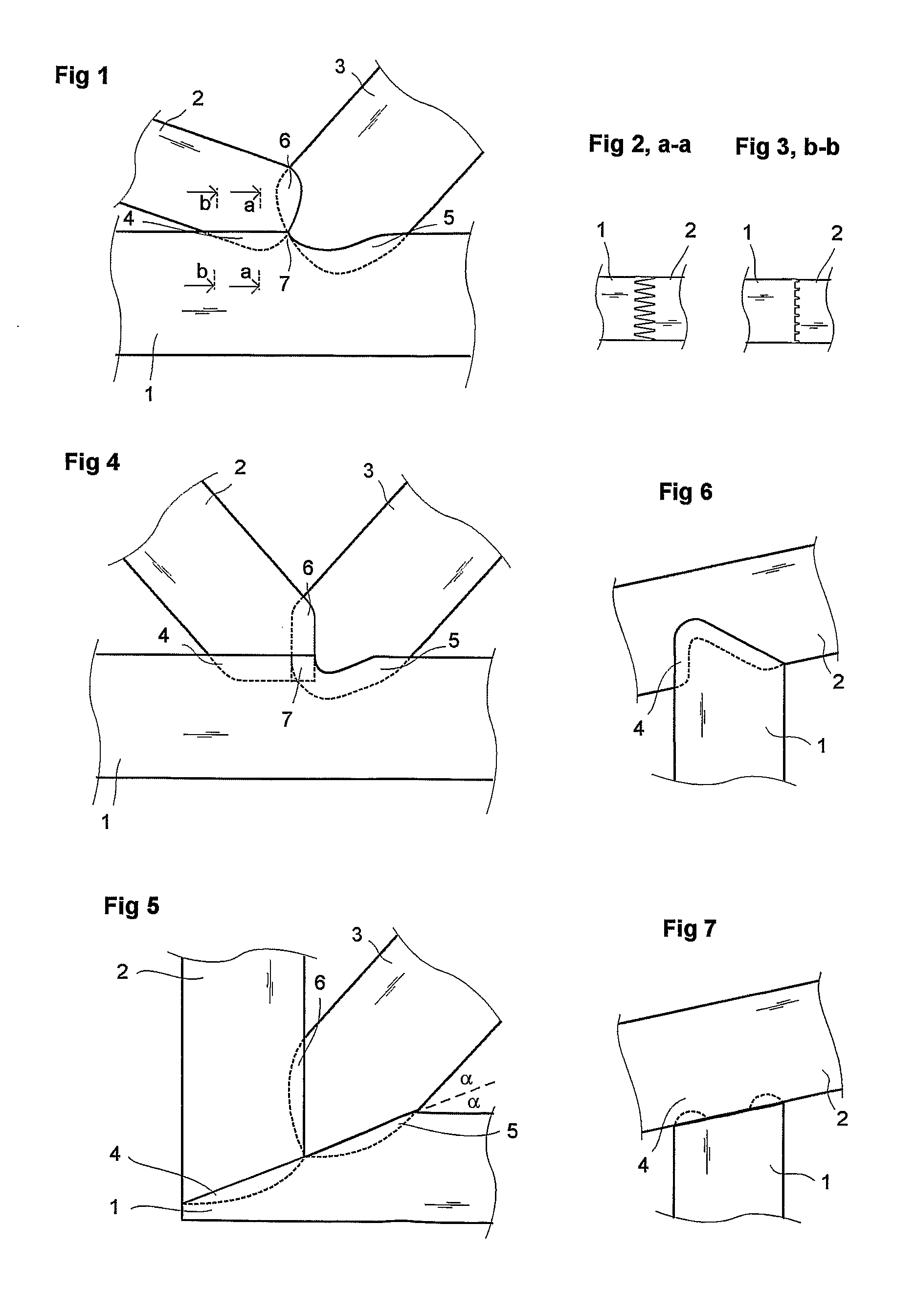
[0038]In FIGS. 1, 2, 3 the finger joint is a diagonal of two wooden parts 2 and 3, as a truss, on the side of the chord of other wooden part 1. FIGS. 2 and 3 show the section of joint area 4 fingers. The fingers get shorter in the ends of the joint area. In this case the fingers of part 2 get thicker while getting shorter. Finger cuttings between parts 4, 5 and 6 are presented with a uniform line, if the cutting groove is visible and with a broken line if the cutting groove (fingertip) is invisible. By cutting 4 from chord 1 wood is removed a little. The cutting height is at its most only the height of the cutters of the cutting cursor or even lower. Often the finger grooves must be cut deeper in the chord than the height of fingers in order to achieve sufficient firmness of joint, especially to prevent cracking rupture in the bottom of the cutting grooves. By cutting 5 the cutting height and the firmness of joint is greater. The solution is advantageous, when minor cutting 4 is fit...


PUM


Abstract

A joint between wood pieces, as of timber, laminated timber, LVL, plywood etc., where one or more bars (2, 3), as the diagonal of a truss, is connected the side of other bar (1), as the side of the truss chord whereby in the produced joint all said bars are connected to each other by a finger joint. From chord (1) wood is cut either so that asymmetrically from the one side less is cut than from the other side or so that from the middle less is cut than from the ends.

Description

FIELD OF INVENTION[0001]The invention relates to a truss joint according to claim 1 and a method according to the preamble of claim 3.BACKGROUND[0002]Previously known are several ways to connect the other bar or several bars on the side of a wooden bar. Such joints are for instance the T- or K-joint between the chord of a wooden truss or between one or more diagonals, for example U.S. Pat. No. 3,507,524, U.S. Pat. No. 1,359,399 and FR 20583315. Hereinafter the connection pieces are called chord and diagonal, although the applications of the new joint are not restricted to trusses, with which, for instance, the said terms are connected. Essential in such a joint is what kind is the joint cutting of chord. This cutting is done with a cutting tool so that in the chord between the ends of the cutting area one or more grooves or fingers are formed in the chord direction. As to its breadth the cutting area can be as broad as the whole chord or only a part of it.[0003]There are in present ...

Claims


Application Information

Patent Timeline
Patent Type & Authority Applications(United States)
IPC IPC(8): B27F1/16E04B1/58E04B7/00E04B1/26E04C3/12B27D1/10B27FE04C3/17
CPCB27F1/16E04B1/2604Y10T403/447E04C3/17Y10T403/7045E04B2001/264
Inventor POUTANEN, TUOMO
Owner POUTANEN TUOMO
Learn More