Harvester Crane

a crane and crane technology, applied in the field of cranes, can solve the problems of disadvantageous position of the loader centre of gravity, the operation of the lifting cylinder, and the danger of being hit by the load, and achieve the effect of easy damag

Active Publication Date: 2008-05-29
PONSSE
View PDF11 Cites 11 Cited by
  • Summary
  • Abstract
  • Description
  • Claims
  • Application Information

AI Technical Summary

Benefits of technology

[0013]First of all, the invention is based on the idea that the lifting operation is implemented by a pushing work movement, with the aid of a lift operating device arranged to rise, so that the dimensions and weight of the operating device will remain reasonable while implementing a lifting force. In order to make the centre of gravity of the crane as low as possible, the lift cylinder is located inside the pedestal of the crane, in such a

Problems solved by technology

When the set of booms is being raised, the lift cylinder operates in compression, but is in danger of being hit by the load.
In addition, the centre of gravity of the loader located disadvantageously high.
In the case of a pulling cylinder, the problem arises of the dimensions of the cylinder becoming unreasonably large in order to create a sufficient lifting force.
In addition, the lift cylinder and the structures connected to it that come under a large tensile strain, particularly the structures made by casting, have proven to be unreliable in practice.
On the other hand, in the ca

Method used


Image

  • Harvester Crane
  • Harvester Crane
  • Harvester Crane

Examples


Embodiment Construction

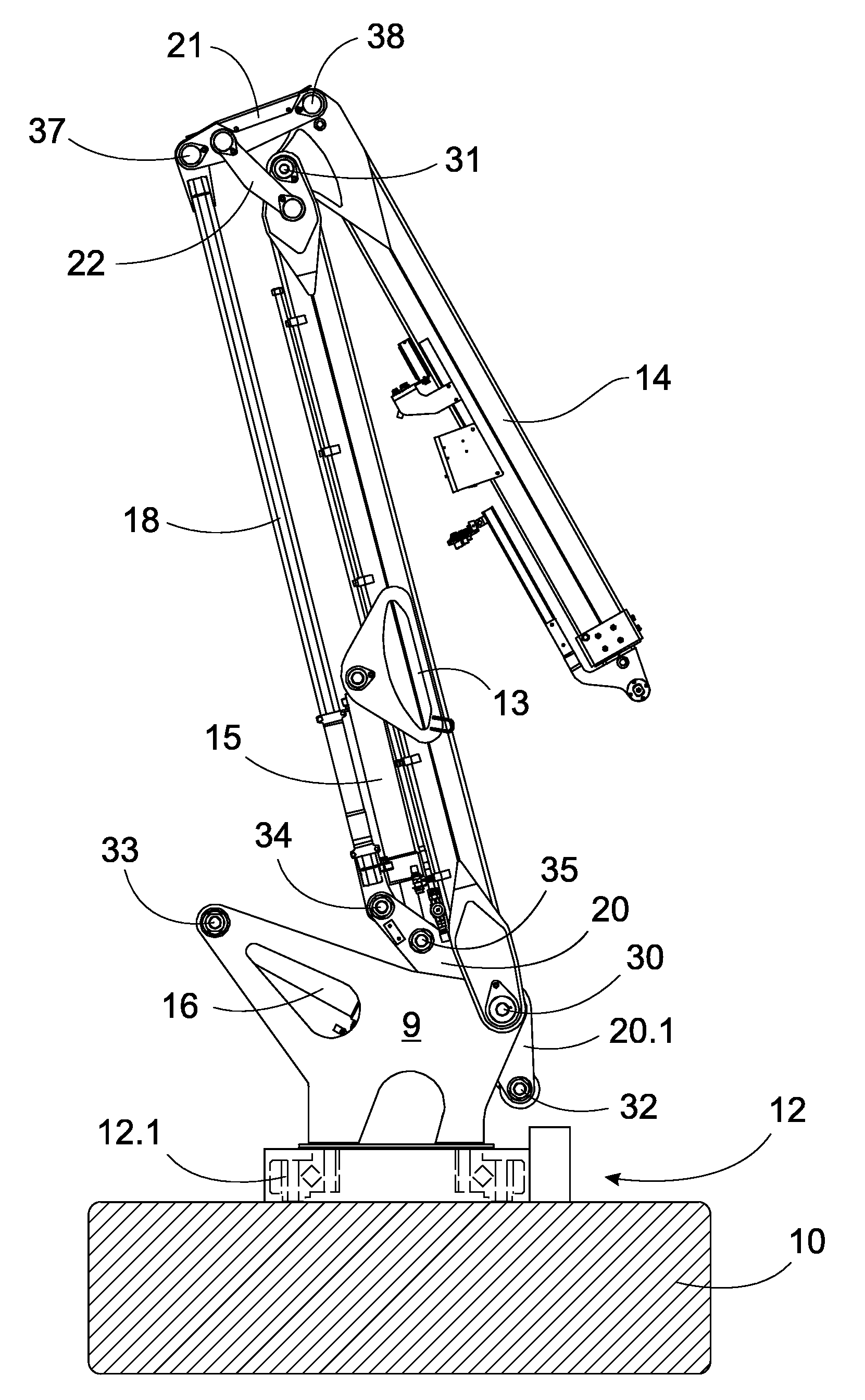
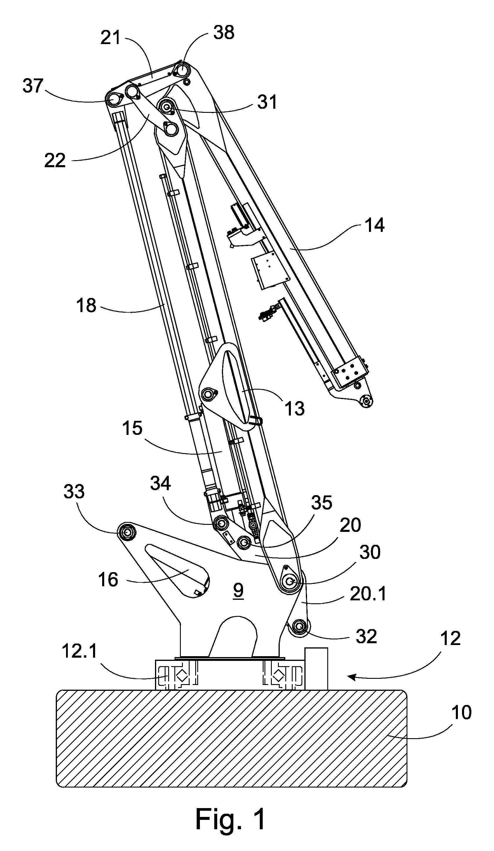
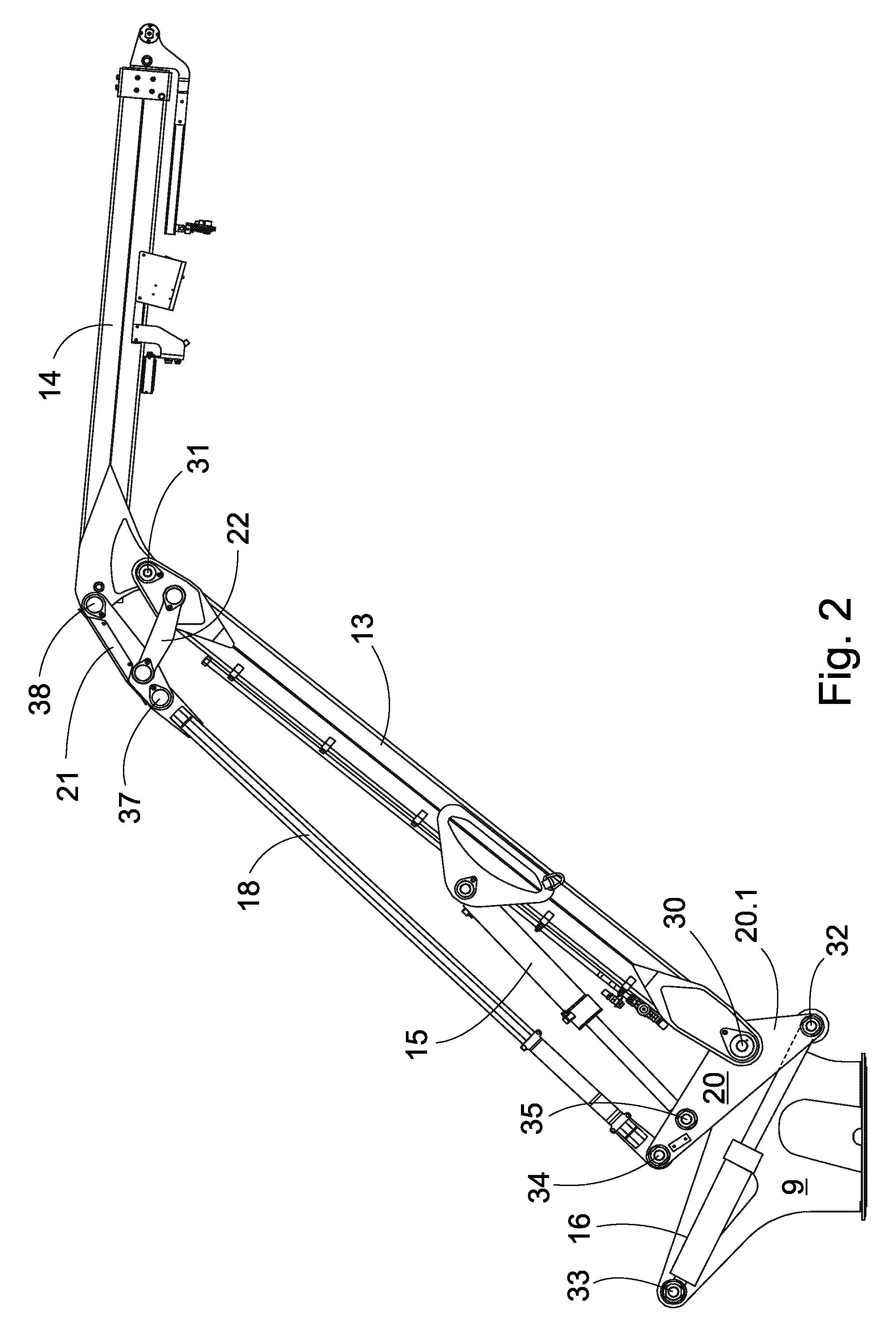
[0024]The crane of FIGS. 1-4 is intended to be installed on the frame of a forestry machine, i.e. generally on a chassis machine, which is marked schematically with the reference number 10 in FIG. 1. The pedestal 9 of the crane is secured through the rotating device 12 to the chassis machine 10. In the rotating device, there is preferably a toothed ring driven by a pinion, and which is on the outer or inner circumference of the ring bearing. One such ring bearing 12.1 is drawn in FIG. 1 by broken lines inside the rotating device 12.

[0025]In one model, the ring bearing used is a stewing ring of the ROLLIX® type. The bearing diameter is 823 mm and the diameter of the outer toothed ring is 962 mm. As the pivot length of the main boom is 4720 mm, the bearing diameter is 17% of this. Generally, the range is 13-25%, preferably 15-20%. For its part, a rotating device with a considerably large diameter and a pinion drive permits a low pedestal structure with a pushing lift cylinder.

[0026]Th...


PUM


Abstract

The invention relates to a harvester crane, which includes a set of booms, which are attached by means of a pedestal and rotating device to a chassis machine, in which the set of booms includes a main boom, which is pivoted at its lower end by a lower pivot to the pedestal; and an articulated boom, which is pivoted by an upper pivot to the opposite end of the main boom and which extends its path mainly forward from the main boom; operating devices, i.e. a lift device and a transfer device, operating the booms. The lower pivot of the main boom is located low down near to the rotating device and the pedestal is fork-shaped, the lower arm and the lift cylinder being located at least partly inside it.

Description

SCOPE OF THE INVENTION[0001]The present invention relates to a harvester crane according to the preamble to claim 1.[0002]As is known, cranes of this kind are used, for example, in forestry machines for moving and processing pieces of timber, or entire trees. In particular, single-grip harvesters use so-called harvester cranes, which can be envisaged as being referred to in the solution according to the invention. The term harvester crane is used generally for at least timber cranes and loaders, the outer point of the set of booms of which, thanks to its pivot geometry, implements some sort of more or less straight movement, preferably essentially horizontally in the area of the reach of the crane, when only one operating device (typically a so-called transfer cylinder) operates.[0003]The loader manufactured by the Swedish company Mowi system AB is very close to the type according to the preamble. In it, the lower arm is situated at the end of a high pedestal column, so that the lif...

Claims


Application Information

Patent Timeline
IPC IPC(8): B66C23/42B66C23/84A01G
CPCB66C23/54
Inventor LEINONEN, YRJO
Owner PONSSE
Why Eureka
Try Eureka