Eureka AIR delivers breakthrough ideas for toughest innovation challenges, trusted by R&D personnel around the world.

Remotely located cryocooler

a cryocooler and remote location technology, applied in the field of propellant replacement systems of spacecraft, can solve the problems of limited and restricted performance, current surface activity modules, and many spacecraft being incapable of performing extended missions or missions, and achieves low cost, efficient and inexpensive techniques, and cost-effective effects

Active Publication Date: 2008-05-29
THE BOEING CO
View PDF6 Cites 28 Cited by
  • Summary
  • Abstract
  • Description
  • Claims
  • Application Information

AI Technical Summary

Benefits of technology

[0011]Embodiments of the invention involve separation of the cryocooler from the tanks of propellant it is tasked with cooling. As taught herein, a remotely located cryocooler provides adequate cryogenic cooling without modifying existing propellant tanks. In addition, this configuration defines a common interface between propellant tanks in a propellant cartridge system and cryocooler. Accordingly, embodiments of the invention reduce the development costs of new propellant tank sets.
[0012]In addition, by locating the cryocooler within the spacecraft bus, distributed systems such as power and thermal radiators are readily available. This approach simplifies cryocooler integration into the propellant tank thermal control system and eliminates development and manufacturing costs of a new propellant tank module that would otherwise be required to provide portable power and sufficient radiator area. A remotely located cryocooler preserves advanced cryocooler equipment and other expensive spacecraft components not discarded along with empty propellant tanks in the propellant cartridge system.
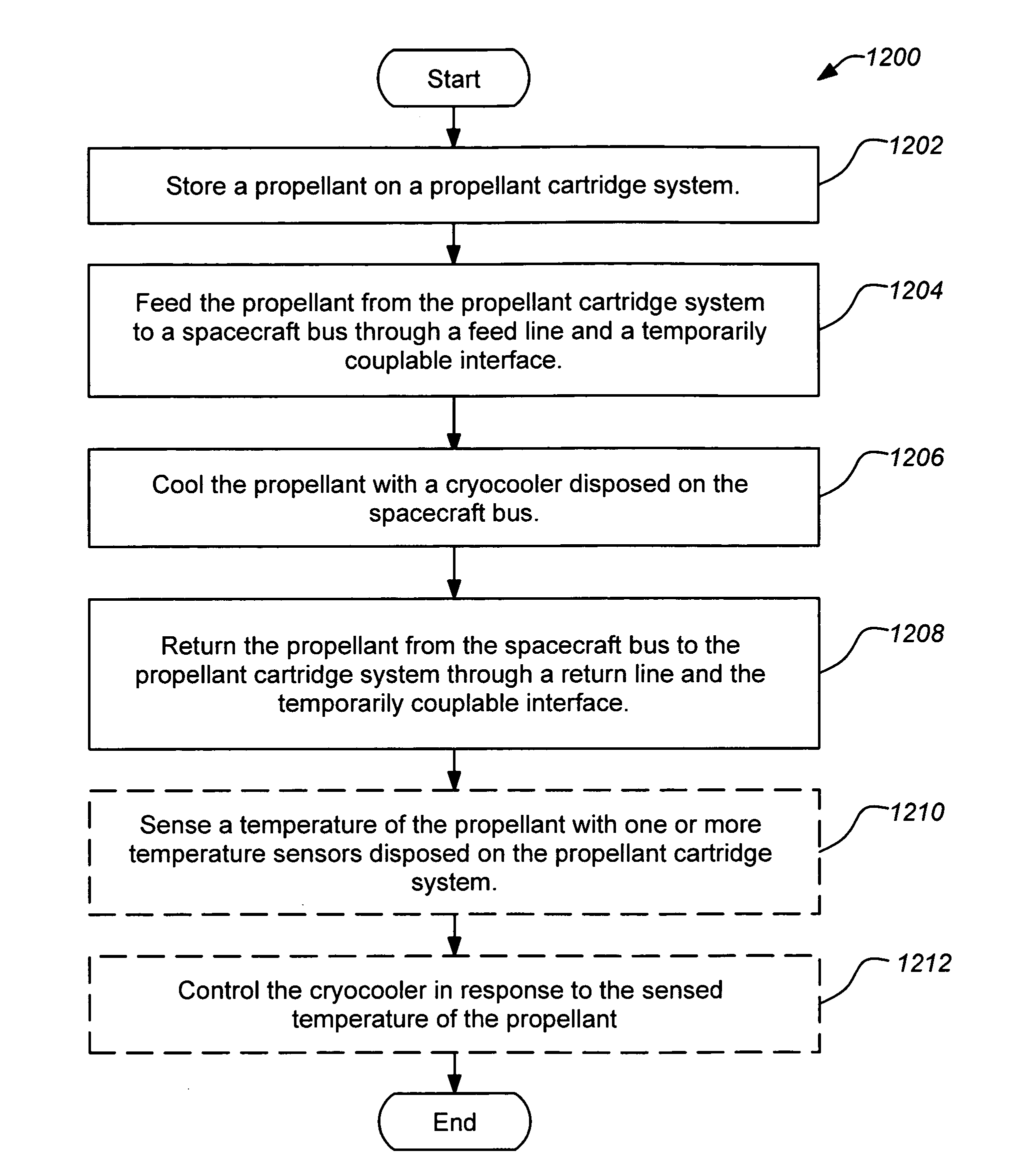
[0016]A typical method embodiment of the invention comprise storing propellant on a propellant cartridge system, feeding propellant from the propellant cartridge system to a spacecraft bus through a feed line and a temporarily couplable interface, cooling the propellant with a cryocooler disposed on the spacecraft bus, and returning the propellant from the spacecraft bus to the propellant cartridge system through a return line and the temporarily couplable interface. The method may further include sensing a temperature of the propellant with one or more temperature sensors disposed on the propellant cartridge system and controlling the cryocooler in response to the sensed temperature of the propellant. Method embodiments of the invention may be further modified consistent with the apparatuses and systems described herein. The various embodiments of the present invention provide several advantages.
[0017]For example, embodiments of the present invention provide the advantage of a cost effective propellant storage solution for spacecraft, particularly for long duration missions. Embodiments of the invention are advantageous for missions requiring significant amounts of propellant, particularly those where propellant resupply is planned. Similarly, embodiments of the invention are advantageous for extended and repeated space flight explorations.
[0018]Yet another advantage provided by an embodiment of the present invention is the provision of an exchangeable propellant cartridge system for an in-space propellant depot. This allows an orbital propellant depot to remain in orbit while only replacing the propellant cartridges associated therewith. Thus, the present invention provides an efficient and inexpensive technique for supplying propellant to a spacecraft in space. The present invention provides relatively low cost propellant tanks that are self-contained and may be replaceable or self-disposing.

Problems solved by technology

Current surface activity modules and spacecraft that require propellant to perform certain tasks, such as flight control, flight translation or orientation through use of thrusters, or other propellant requiring tasks, are performance limited and restricted due to the limited amount of propellant available onboard.
As such, many spacecraft are incapable of performing extended missions or missions that require a substantial amount of propellant consumption over a short duration of time.
In addition, there are vehicle weight and size restrictions and limitations, as well as significant costs associated with the launching of a vehicle, which are directly related to the amount of propellant that the vehicle is carrying onboard.
The more propellant a vehicle is carrying, generally, the heavier the vehicle, the larger the vehicle, and the more propellant required and the higher the costs associated with the launch of that vehicle.
Moreover, there are overall limitations upon which the launching of such a vehicle becomes impractical or infeasible.
Cryocoolers are used to maintain stored cryogenic propellant at a proper temperature present a particular problem in spacecraft design.
However, this approach is expensive because space qualified cryocoolers have higher development and manufacturing costs than the cryogenic propellant tanks they are designed to cool.

Method used


Image

  • Remotely located cryocooler
  • Remotely located cryocooler
  • Remotely located cryocooler

Examples


Embodiment Construction

1. Overview

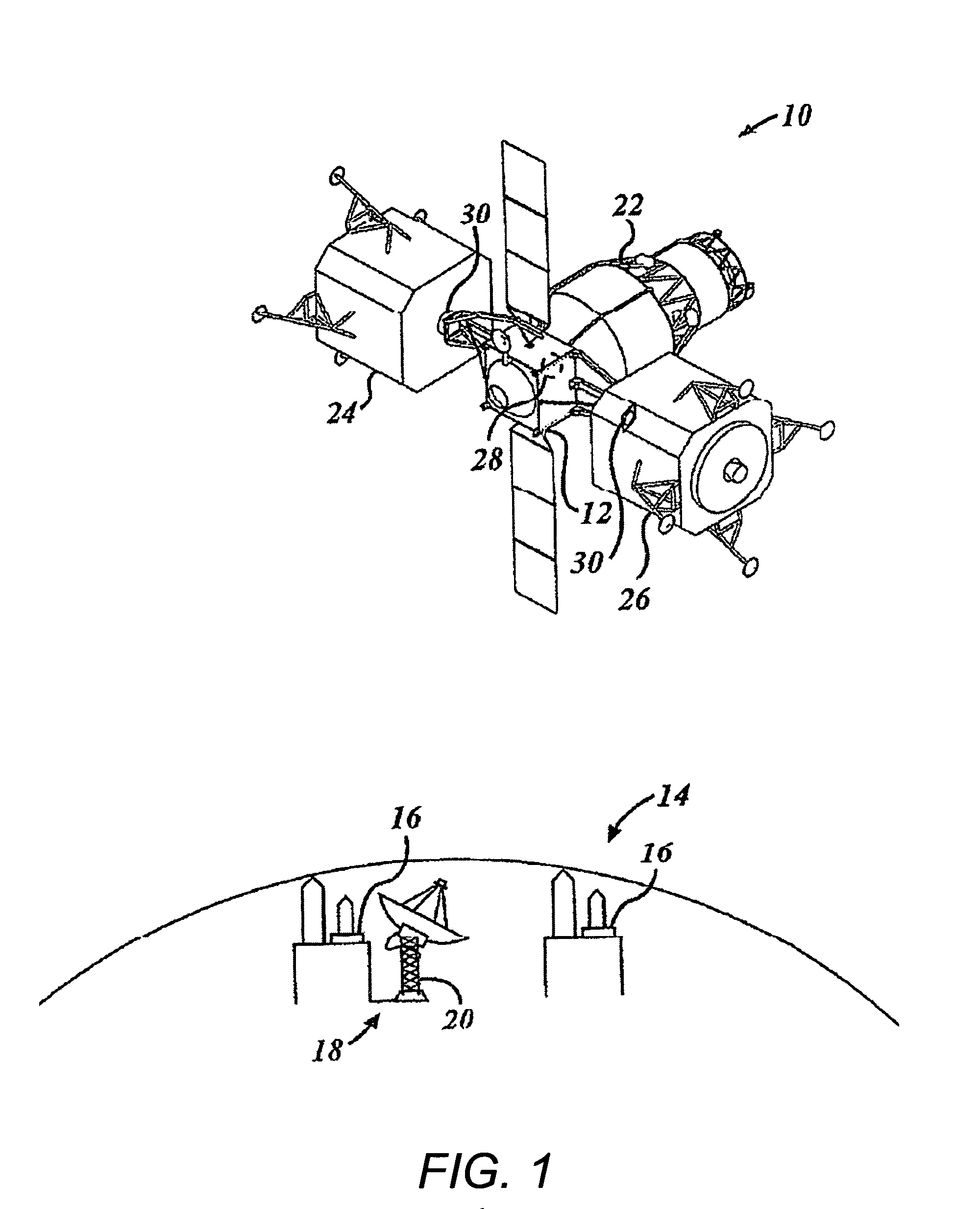
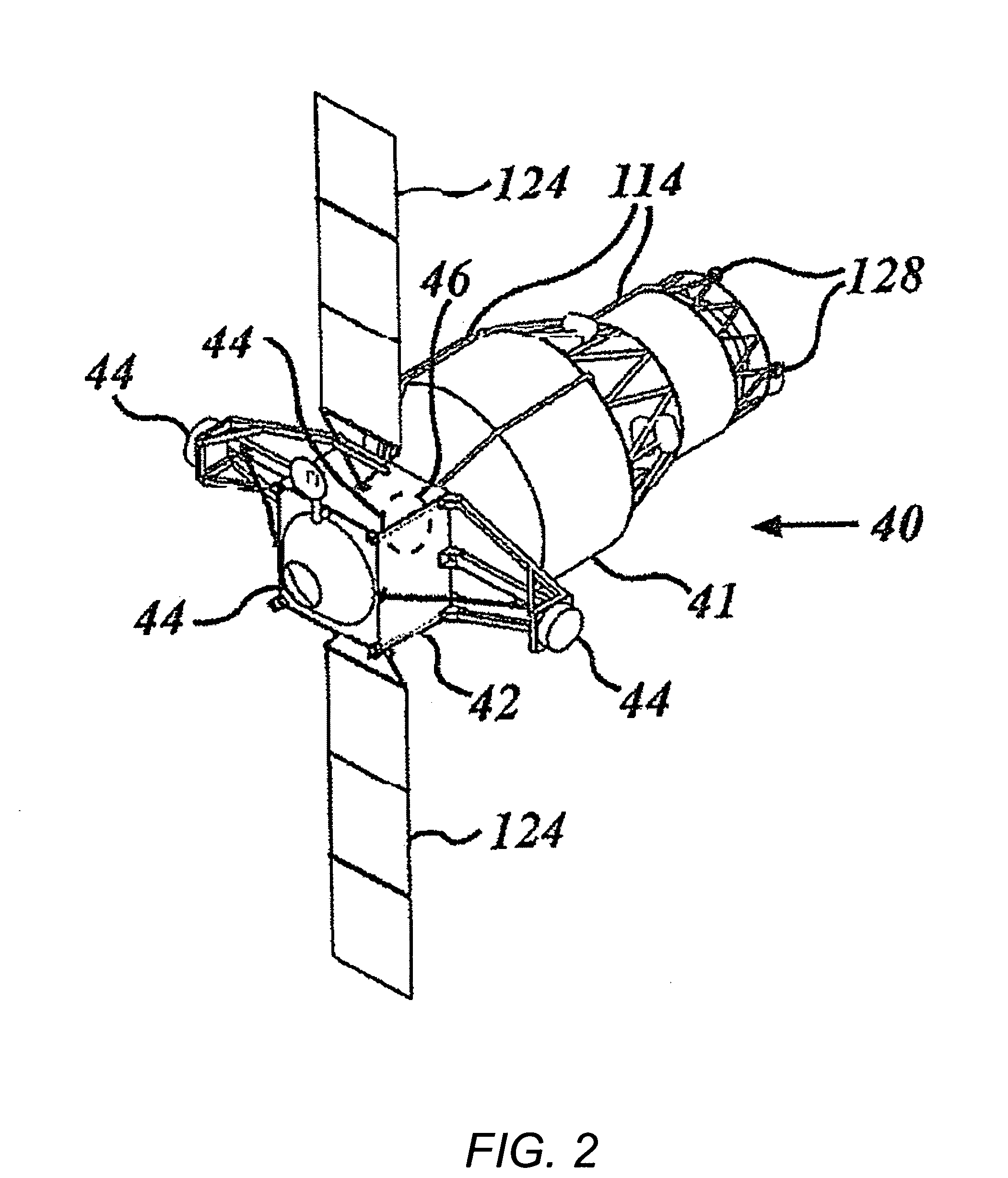
[0033]The cryocooler may be located in a standard spacecraft bus (such as a spacecraft bus box) along with other standard spacecraft elements known in the art (e.g. communications, power generation and distribution, navigation, data handling, thermal management, etc). The cryogenic propellant tanks may then comprise a separable and distinct propellant cartridge system docked to the spacecraft bus containing the cryocooler. Insulated lines run from the cryogenic tanks to the cooling interface (or cold heat exchanger) of the cryocooler. In operation, propellant (e.g. fuel and / or oxidizer) may be continuously pumped from the tanks through the cryocooler cold heat exchanger and then back to the tanks on the separable propellant cartridge system spacecraft. After the propellant tanks are depleted, the cryocooler may be switched off and supply / return lines disconnected. The propellant cartridge system is then undocked from the bus (and typically discarded). A new propellant car...


PUM


Abstract

A cryocooler is located on a spacecraft bus, such as a bus box, separate from the cryogenic propellant tanks disposed on a separable and distinct propellant cartridge system spacecraft docked to the spacecraft bus. In operation, propellant may be continuously pumped from the tanks through the cryocooler cold heat exchanger and then back to the tanks on the separable propellant cartridge system spacecraft through temporarily couplable lines. After the propellant tanks are depleted, the propellant cartridge system is then undocked from the bus and typically discarded. A new propellant cartridge system spacecraft comprising a full set of tanks may then be docked to the bus and the cryocooler supply / return lines coupled. The remote cryocooler may function as part of a larger space depot for spacecraft resupply, although it is not limited to such applications.

Description

CROSS-REFERENCE TO RELATED APPLICATIONS[0001]This continuation-in-part application claims the benefit under 35 U.S.C. §120 of the following co-pending U.S. utility patent application, which is incorporated by reference herein:[0002]U.S. patent application Ser. No. 11 / 162,333, filed Sep. 7, 2005 by Behrens et al. and entitled “SPACE DEPOT FOR SPACECRAFT RESUPPLY”.BACKGROUND OF THE INVENTION[0003]1. Field of the Invention[0004]The present invention relates generally to spacecraft propellant replacement systems. More particularly, the present invention is related to the propellant cooling system on a spacecraft, such as a lunar or non-earth surface activity module or a crew exploration vehicle.[0005]2. Description of the Related Art[0006]Systems and devices used in space flight and exploration, such as non-Earth surface activity modules and other spacecraft, are continuously being researched and developed for various purposes. Surface activity modules, such as a lunar surface activity ...

Claims


Application Information

Patent Timeline
IPC IPC(8): B64G1/64
CPCB64G1/1078B64G1/646B64G1/402Y10T137/6855B64G1/64
Inventor BEHRENS, JOHN W.CHANDLER, FRANK O.CRONICK, JEFFREY J.LOPEZ, ALFREDO
Owner THE BOEING CO
Why Eureka
Eureka Blog
Learn More