Holographic microfabrication and characterization system for soft matter and biological systems

Active Publication Date: 2008-05-29
NEW YORK UNIVERSITY
View PDF35 Cites 42 Cited by
  • Summary
  • Abstract
  • Description
  • Claims
  • Application Information

AI Technical Summary

Benefits of technology

[0005]One Three dimensional assembly, micromanipulation and dynamic configuring of objects is accomplished by use of computer generated holograms which can trap objects, exert precision force at selected system locations and assemble complex arrangements of objects in any selected three dimensional configuration, including extensive stacks of objects. Collectively the assembly of optical traps can execute processing and manufacturing protocols for a wide variety of commercial purposes. This system can carry out such manufacturing steps as assemblying three dimensional functional structures from various building blocks, such as microscopic fluid-borne objects (colloidal particles, e.g.), macromolecules, nanoclusters, nanowires

Problems solved by technology

In view of all these degrees of freedom, however, little has

Method used


Image

  • Holographic microfabrication and characterization system for soft matter and biological systems
  • Holographic microfabrication and characterization system for soft matter and biological systems
  • Holographic microfabrication and characterization system for soft matter and biological systems

Examples


Embodiment Construction

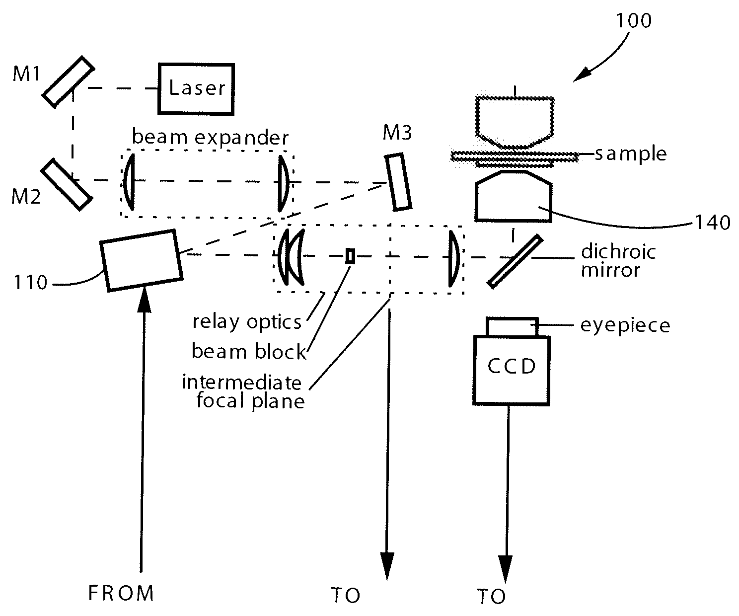
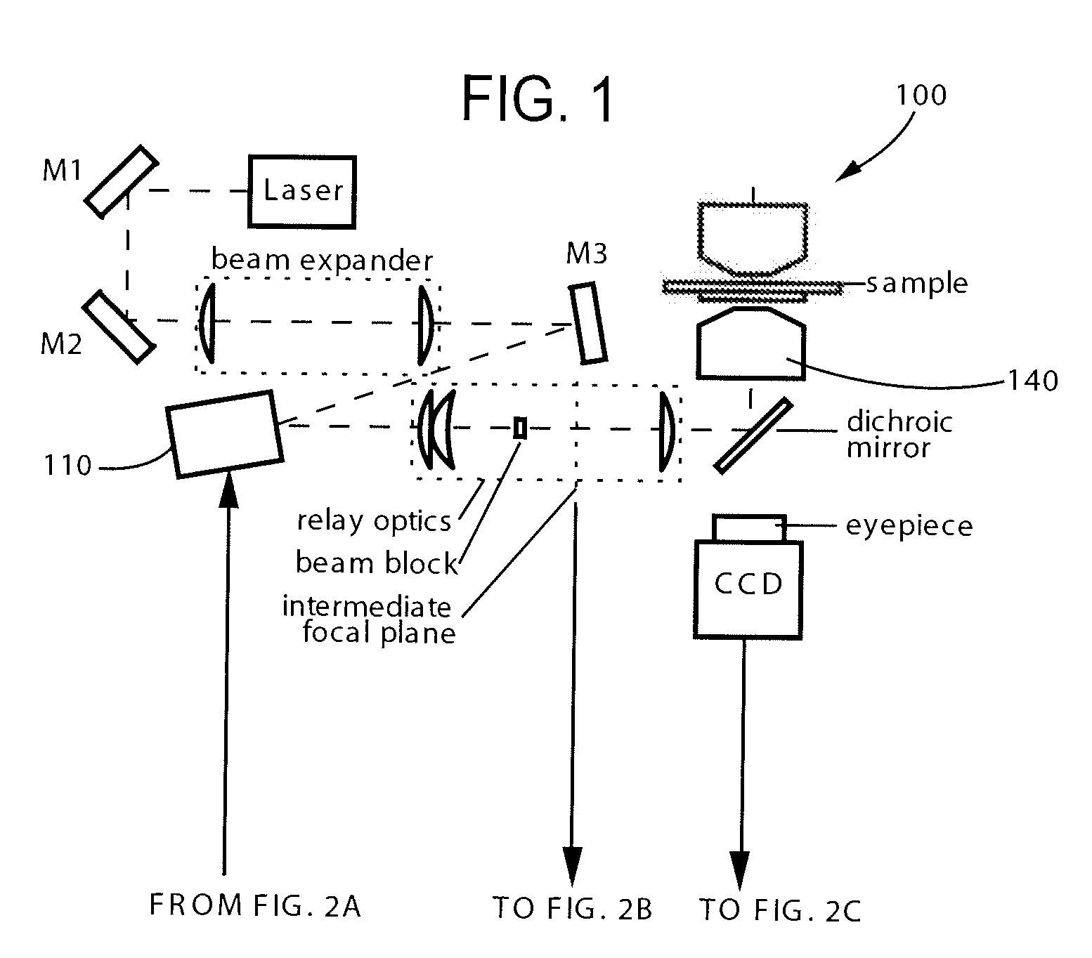
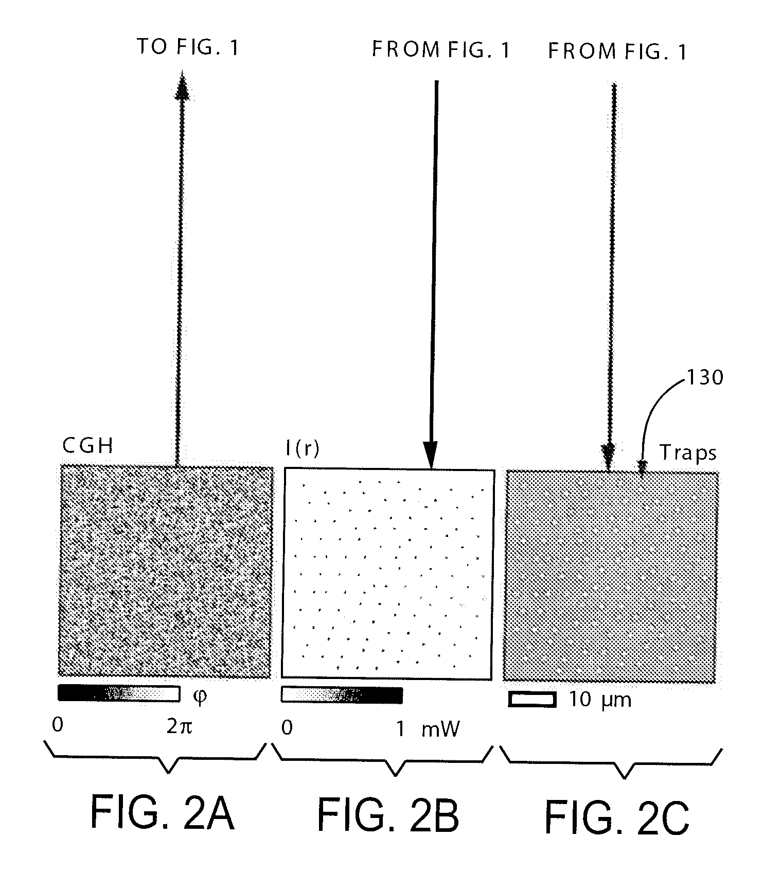
[0017]A system constructed in accordance with an embodiment of the invention is shown generally at 100 in FIG. 1. The system 100 uses a computer-designed diffractive optical element (DOE) 110 to split a single collimated laser beam 120 into multiple independent beams, each of which subsequently is focused into an optical trap or tweezers 130 (see FIG. 2C) preferably by a strongly converging objective lens 140 in FIG. 1. The DOE 110 preferably takes the form of a spatial light modulator (SLM) to create a computer-generated hologram (CGH) as shown in FIG. 2A. This CGH creates a plurality of light beams 125 in FIG. 2B specifically designed to create a particular pattern of the optical tweezers 130 (see FIG. 2C). Projecting a sequence of computer-designed holograms with an SLM reconfigures the projected traps 130, thereby translating trapped particles or manipulating objects along selected independent paths. The optical tweezer 130 is created in a conventional manner by bringing an inte...


PUM


Abstract

A method and system for micromanipulation of objects of any shape. The method and system creates various forms of holographic optical traps for a variety of commercial purposes. Some alternate forms of traps include a dark form of optical traps, optical vortices with different helical winding numbers and optical traps with variable phase profiles imprinted thereon.

Description

CROSS-REFERENCE TO RELATED PATENT APPLICATIONS[0001]This application claims the benefit under 35 USE 119(3) of U.S. Application No. 60 / 857,348, filed Nov. 7, 2006, incorporated herein by reference in its entirety.[0002]The United States Government has certain rights in this invention pursuant to grants from the National Science Foundation by Grant Numbers DMR-0451589 and DBI-0629584.[0003]This invention is directed to a fully integrated holographic microfabrication system and method. More particularly, the invention is directed to an optical system for assembling and dynamically controlling complex three dimensional structures from objects suspended in a fluid, the objects being, for example, colloidal particles, macromolecules, nanoclusters, nanowires and biological materials, such as cells. Such objects can be of any size and shape which are readily assembled and manipulated for a selected commercial purpose.BACKGROUND OF THE INVENTION[0004]The use of optical traps or tweezers has...

Claims


Application Information

Patent Timeline
IPC IPC(8): H05H3/00G03H1/08G02B5/32
CPCG02B5/001G02B5/32G03H2001/0077G03H1/08G03H1/2294G02B21/32
Inventor GRIER, DAVID G.
Owner NEW YORK UNIVERSITY
Why Eureka
Try Eureka