
Phase-transition polymeric microneedles

a polymer and phase-transition technology, applied in the field of polymeric microneedle patch, can solve the problems of skin irritation, delay the recovery of skin punched holes, and the cost of micro-needle arrays made by mems technology,

Active Publication Date: 2011-08-11
JIN TUO
View PDF5 Cites 60 Cited by
  • Summary
  • Abstract
  • Description
  • Claims
  • Application Information

AI Technical Summary

Benefits of technology

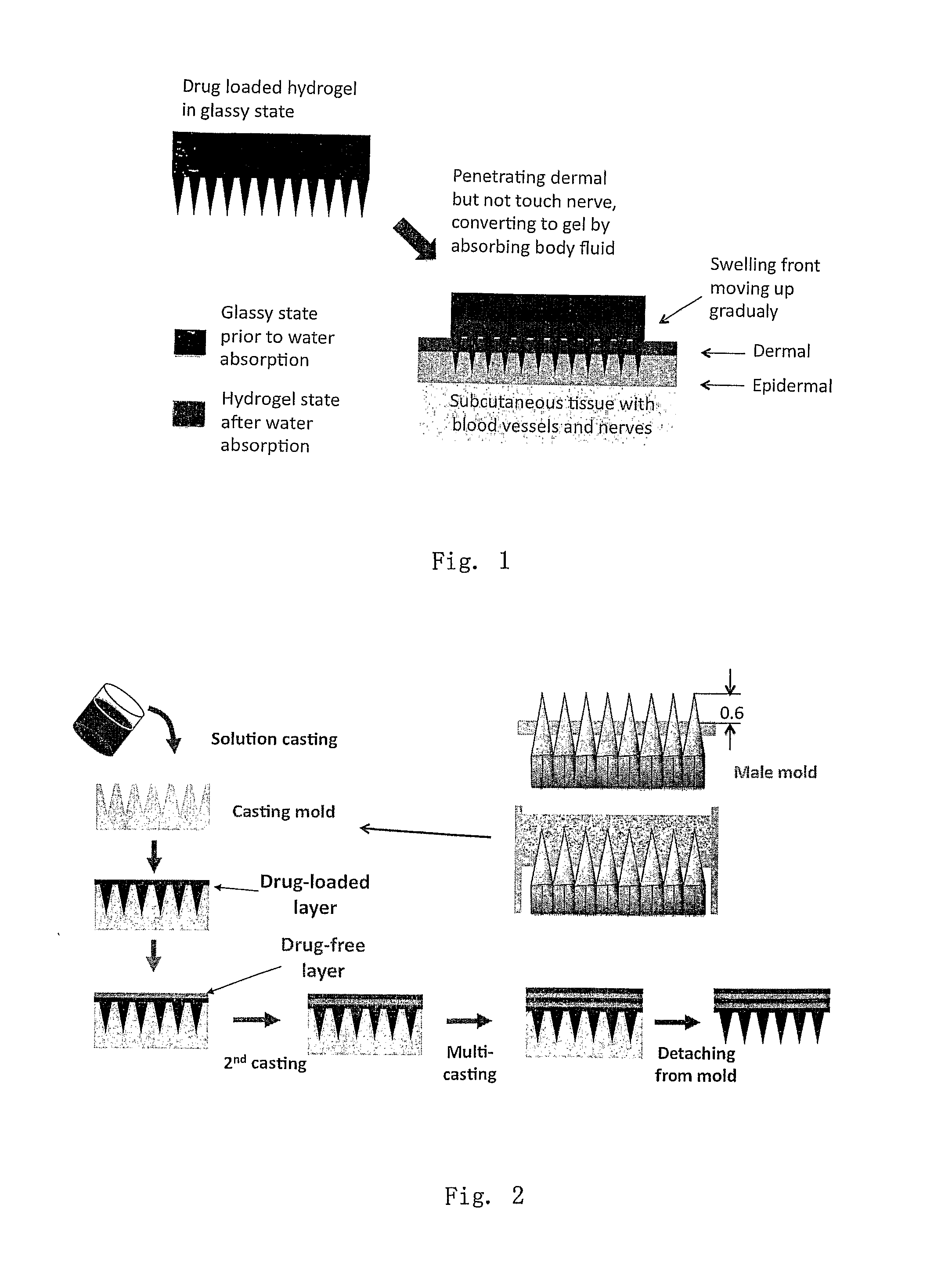
[0012]In addition to the phase transition nature, one important advantage of this microneedle array system is its easy yet multi-functional fabrication process. The microneedle array can simply be prepared by casting an aqueous solution of the microneedle-forming polymer on a mold having microholes aligned on its surface as an array. The final form of the microneedle patch is formed by drying the casted solution and detached it from the mold. Drugs to be delivered are added into the polymer solution before casting on the mold. A unique and interesting feature of this system is that its fabrication process can be used to achieve a desired release pattern. By a programmed casting (i.e. casting polymer solutions with different drug concentration stepwise on the mold), a precisely programmed drug release profile can be achieved. FIG. 2 describes the process of programmed casting schematically.
[0014]The programmed casting technology may also allow us to prepare microneedle patches with hard needles and soft holding plate (even at dry state) by using different polymer solutions for respective layers of casting. This type patched may be preferred for skin care applications because the patches may fit the contours (outlines) of human faces.

Problems solved by technology

From a practical point of view, however, micro-needle arrays made by MEMS technology are too expensive as a daily disposable dosage form.
This may cause skin irritation and delay the recovery of skin punched holes by the needles.
In case the needles break and leave metal or other inorganic particles in the skin, more serious skin irritation may be induced.
In addition, protein therapeutics stored in the reservoir in solutions state may have stability problem when they are attached on skin at body temperature.
The punch-drop type of drug administration is, however, compromised with lack of control in dose and skin up-take of the drug.
These systems, however, are still incapable to offer a sustained or controlled release drug delivery.
The problem by incident closing of the microholes remains.
However, degradation of PLA, PGA and PLGA is often too slow to deliver drug at required rate.
In addition, loading proteins in a hydrophobic matrix may cause the macromolecules to denature.
This type of microneedle arrays offer a well-defined dose of drug, but are not able for a sustained or controlled delivery over a prolonged period of time since the holes may close after the needles are dissolved.

Method used


Image

  • Phase-transition polymeric microneedles
  • Phase-transition polymeric microneedles
  • Phase-transition polymeric microneedles

Examples


example 1

Preparation of Phase-Transition Microneedle Patch Using Polyvinyl Alcohol (PVA) and Dextran

[0044]A mixed aqueous solution of PVA (15% by weight in concentration and 10,000-250,000 in weight-average molecular weight) and dextran (0-3% by weight in concentration and 6,000-5,000,000 in weight-average molecular weight) was casted on a gypsum mold consisting of an array of microholes. After casting the polymer solution on the mold, vacuum was applied on the other side of the mold to suck the polymer solution into the microholes. Drugs to be delivered (such as insulin) were added in the mixed polymer solution before casting onto the mold. After filling the microholes with the polymer solution, the sample was cooled to freeze the water-based solution. The sample may be frozen again after it is warmed up to room temperature and the freeze-thaw treatment may be repeated several time to adjust the density of the crystalline cross-linking junctions of PVA. Then, the top surface of the polymer ...

example 2

Release Kinetics of Insulin from Microneedle Patches

[0047]To test release profiles of insulin, the microneedle patches prepared as above were attached to a model skin mounted on a Franz diffusion cell filled with PBS buffer at pH 7.4 being stirred at 100 rpm (as the receiving pool). The patch was covered with plastic film to prevent water evaporation from the top. Release kinetics of insulin from the patch was examined at 37° C. by assaying the insulin concentration change in the PBS buffer. Sample was taken from the receiving cell at a programmed time and assayed for insulin concentration using HPLC. Profiles of the cumulative release of insulin from the phase-transition microneedle patches formed via various cycles of freeze-thaw treatment and formed of PVA and dextran at various ratio are shown in FIG. 5 and FIG. 6, respectively.

[0048]FIG. 5 shows the cumulative release profiles of the patches prepared at fixed PVA / dextran weight ratio (80 / 20) and varied freeze-thaw cycles (2,4 a...

example 3

Preparation of Layered Phase-Transition Microneedle Patches Via Programmed Casting (Molding)

[0049]Two methods were used to prepare layered phase-transition microneedle patches: repeated casting and assembling of pre-formed sheets. For whatever the method, the layer of microneedle array formed by casting a polymer solution on the mold having an array of microholes. For the repeated-casting method, a layer of drug-free solution (or drug-reduced solution) was casted on the top of the first layer after the freezing treatment (some time the freezing step was omitted). This operation was repeated several times till the designed structure was achieved. FIG. 2 shows the fabrication process schematically. The drug concentration and thickness of each layer may be varied to achieve designed release profiles.

[0050]For the assembly method (not shown by figures), after the drug-free or drug-reduced solution was casted on the top of the layer of microneedle array, a pre-formed drug-loaded PVA-dext...


PUM

PropertyMeasurementUnit
Temperatureaaaaaaaaaa
Molar densityaaaaaaaaaa

Abstract

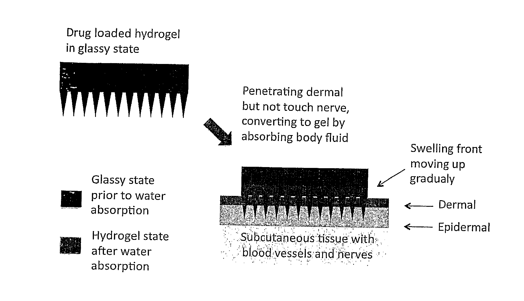
This invention discloses a novel microneedle system, phase-transition microneedle patch, which overcomes all the limitations that existing microneedles encountered. The microneedle patch is formed of an integrated polymeric piece consisting of a microneedle array and a plate (called holding plate) on which the needles stand. The microneedles of the patch are hard and strong enough to penetrate epidermis at dry state but turn to be hydrogel state soft and permeable to hydrophilic agents when absorbing body fluid. The hydrogel state of the patch is a hydrophilic network held by physical or chemical cross-linking junctions. The pores of the network are opened up by body fluid for drugs and macromolecules to diffuse through. The polymeric materials used to form the microneedle patch have been used in the pharmaceutical field for years and have proven compatibility with the skin and with proteins. The drugs may be stored in the matrix of the microneedle array as well as the holding plate so that the requirement for high dose applications may be full filled. In addition, molding (casting) of this type of microneedle patch is simple, easy to achieve and needs no microfabrication systems and organic solvents. By a programmed molding (casting), the patch may be assembled in a layered structure with desired drug concentration in each layer, respectively. Due to this design, a programmed pulse or a zero order release of drugs may easily be achieved. In addition, delicate proteins loaded in the patch are kept in a dry and hydrophilic glassy state before being released, the most favored state for protein storage. Finally, during the swelling-based drug release, the microneedle patch increases their thickness gradually between the skin and the back cover (which holds the needles) lo create a sustained pressure to ensure good contact of the microneedles inside epidermis.

Description

CROSS REFERENCE AND RELATED APPLICATIONS[0001]This application claims priority of U.S. Ser. No. 61 / 103,560 filed Oct. 7, 2008, the contents of which are incorporated by reference here into this application.[0002]Throughout this application, reference is made to various publications. The disclosures of these publications, in their entireties, are hereby incorporated by reference into this application to more fully describe the state of the art to which this invention pertains.FIELD OF THE INVENTION[0003]The present invention describes a polymeric microneedle patch which overcomes the limitations of existing microneedles systems and may be used for transdermal delivery system for therapeutics and other applications. The microneedles of this polymeric microneedle array are sufficiently hard and strong to penetrate skin at dry state but turn to hydrogel form when absorb body fluid or water. This system offers sufficient cross-skin permeability and controlled release delivery of hydrophi...

Claims


Application Information

Patent Timeline
IPC IPC(8): A61K9/00A61K38/00A61K39/00A61K48/00A61K38/28A61P3/10B29C39/42B29C35/16
CPCA61K9/0021A61M37/0015A61M2037/0053A61M2037/0046A61M2037/0023A61P3/10
Inventor JIN, TUO
Owner JIN TUO
Learn More