

Control apparatus for vehicular drive apparatus
- Summary
- Abstract
- Description
- Claims
- Application Information
AI Technical Summary
Benefits of technology
Problems solved by technology
Method used
Image

Examples
first embodiment
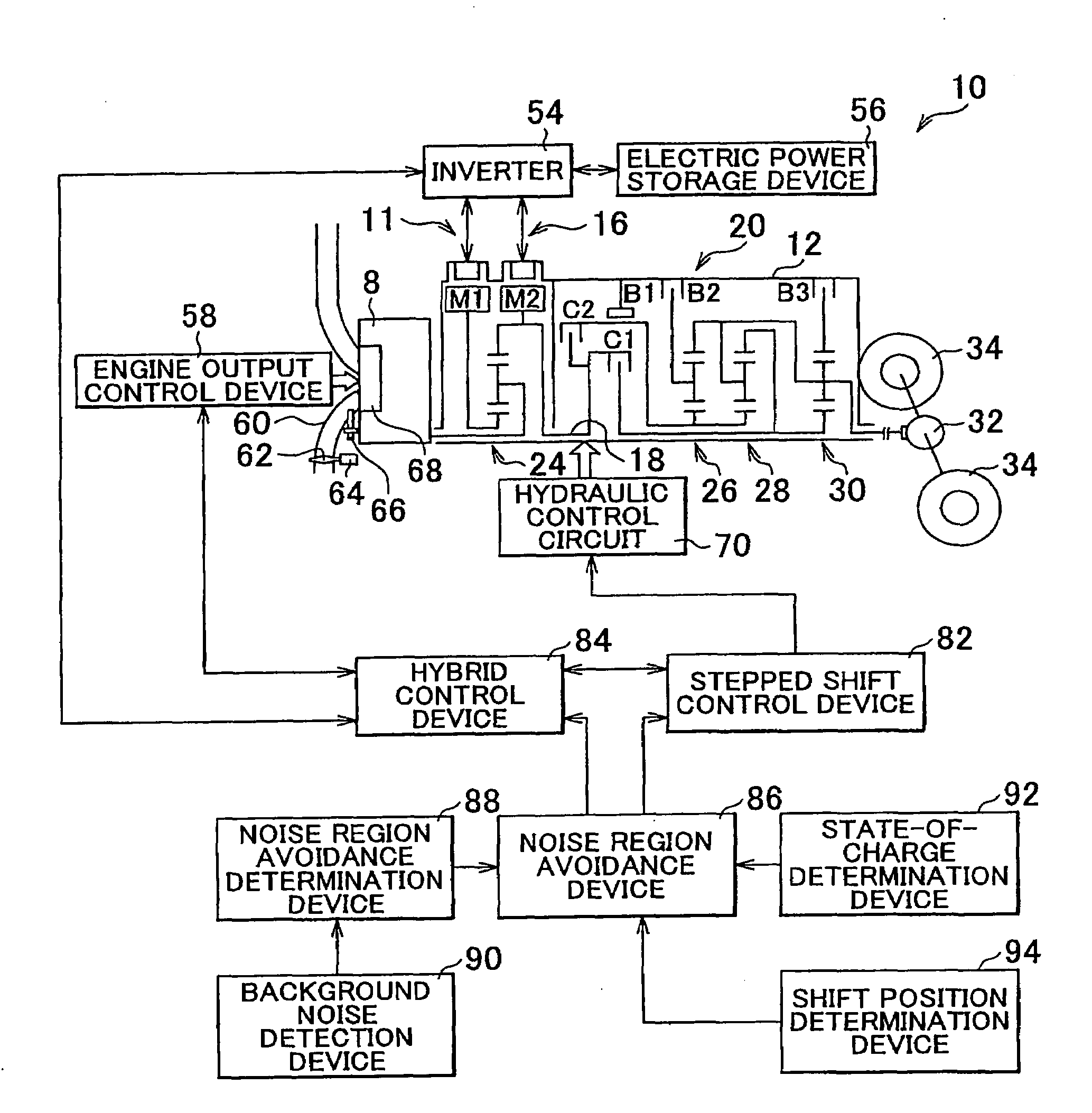
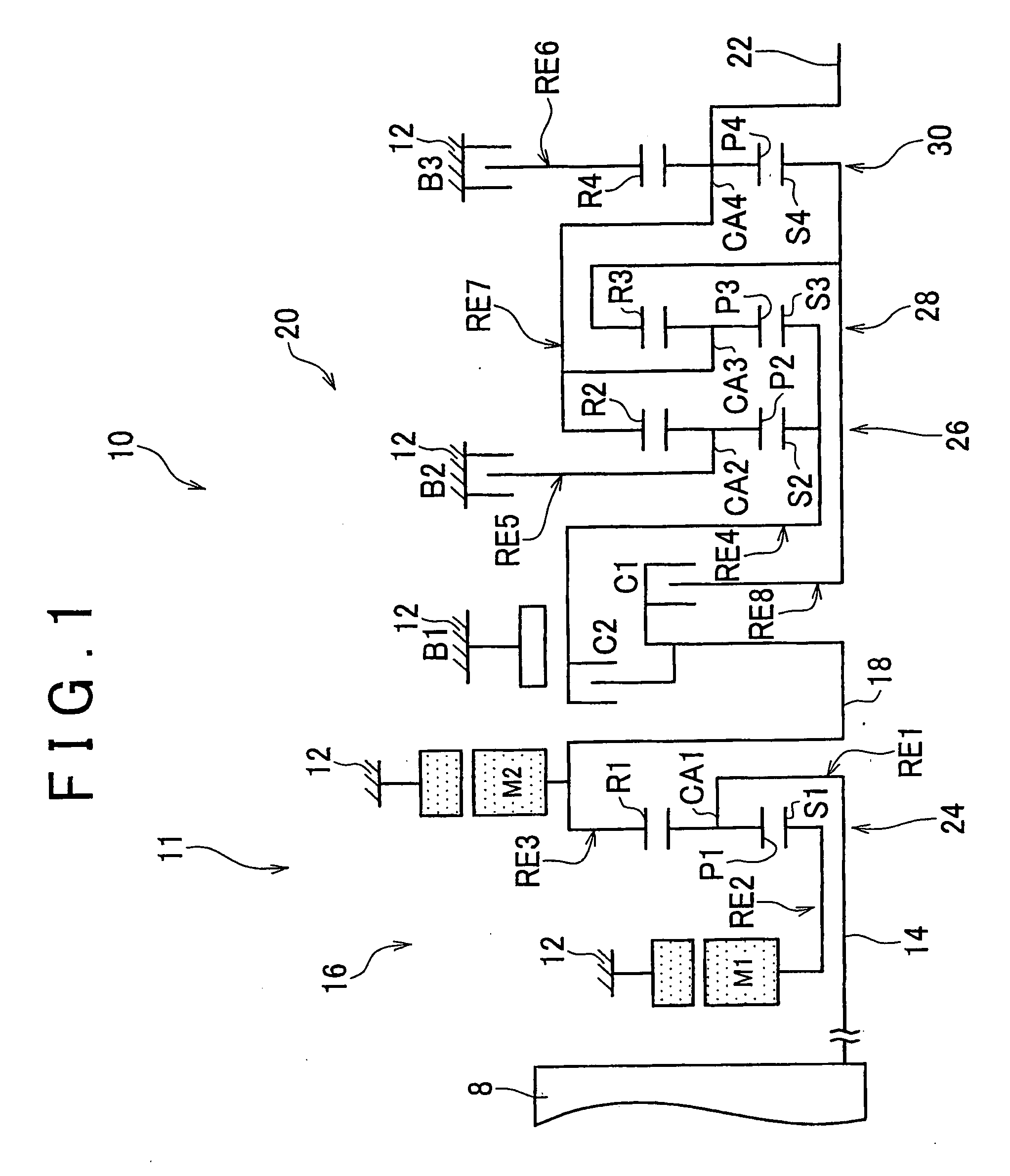
[0039]The differential portion 11 includes a first motor M1, a power split mechanism 16, and a second motor M2. The power split mechanism 16 is a mechanical mechanism that mechanically distributes the output from the engine 8, which is input to the input shaft 14. That is, the power split mechanism 16 is a differential mechanism that distributes the output from the engine 8 to the first motor M1 and the transmitting member 18. The second motor M2 is operatively connected to the transmitting member 18 so that the second motor M2 is rotated integrally with the transmitting member 18. Each of the first motor M1 and the second motor M2 in the first embodiment is a so-called motor-generator that has the function of generating electric power (power-generation function). The first motor M1 has at least the power-generation function for bearing a reaction force. The second motor M2 has at least a motor function for outputting the driving power as the driving power source. In this specificat...
second embodiment
[0134]In the second embodiment, the noise region avoidance device 86 changes the speed ratio γ of the automatic shift portion 20 by changing the shift lines from the normal shift lines to the noise avoidance shift lines. Therefore, it is possible to easily avoid the noise occurrence region N.
[0135]In the second embodiment, the noise region avoidance device 86 changes the shift lines from the noise avoidance shift lines to the normal shift lines, when it is determined that the speed ratio γ of the automatic shift portion 20 will not be changed by changing the shift lines. Therefore, it is possible to avoid the situation where, for example, a downshift is performed and shock is suddenly caused by changing the shift lines to the normal shift lines, and the occupant feels discomfort.
[0136]Next, a third embodiment will be described. FIG. 18 is a schematic diagram explaining the configuration of a shift mechanism 100 according to the third embodiment of the invention. FIG. 19 is an engage...
PUM
 Abstract
Description
Claims
Application Information