Magnetic attraction preventive system

a preventive system and magnet technology, applied in the direction of magnetic variable regulation, process and machine control, instruments, etc., can solve the problems of threaten damage to the object or the apparatus, human errors will occur at a probability of 310, and it is impossible to completely remove human errors, so as to prevent the magnetic attraction of the magnetic material

Inactive Publication Date: 2008-05-29
TOSHIBA MEDICAL SYST CORP
View PDF6 Cites 21 Cited by
  • Summary
  • Abstract
  • Description
  • Claims
  • Application Information

AI Technical Summary

Benefits of technology

[0010]According to a first aspect of the present invention, there is provided a magnetic attraction preventive system comprising: an approach detection unit which generates an approach detection magnetic field and detects the approach of a magnetic material to a magnetic resonance imaging apparatus on the basis of a variation in the strength of the approach detection magnetic field; and a preventive unit which prevents magnetic attraction of the magnetic material to the magnetic resonance imaging apparatus when the approach detection unit detects the approach of the magnetic material to the magnetic resonance imaging appara...

Problems solved by technology

The collision of the object with the magnetic resonance imaging apparatus may cause or threaten damage to the object or the apparatus.
However, it is said that human errors will occur at a probab...

Method used


Image

  • Magnetic attraction preventive system
  • Magnetic attraction preventive system
  • Magnetic attraction preventive system

Examples


first embodiment

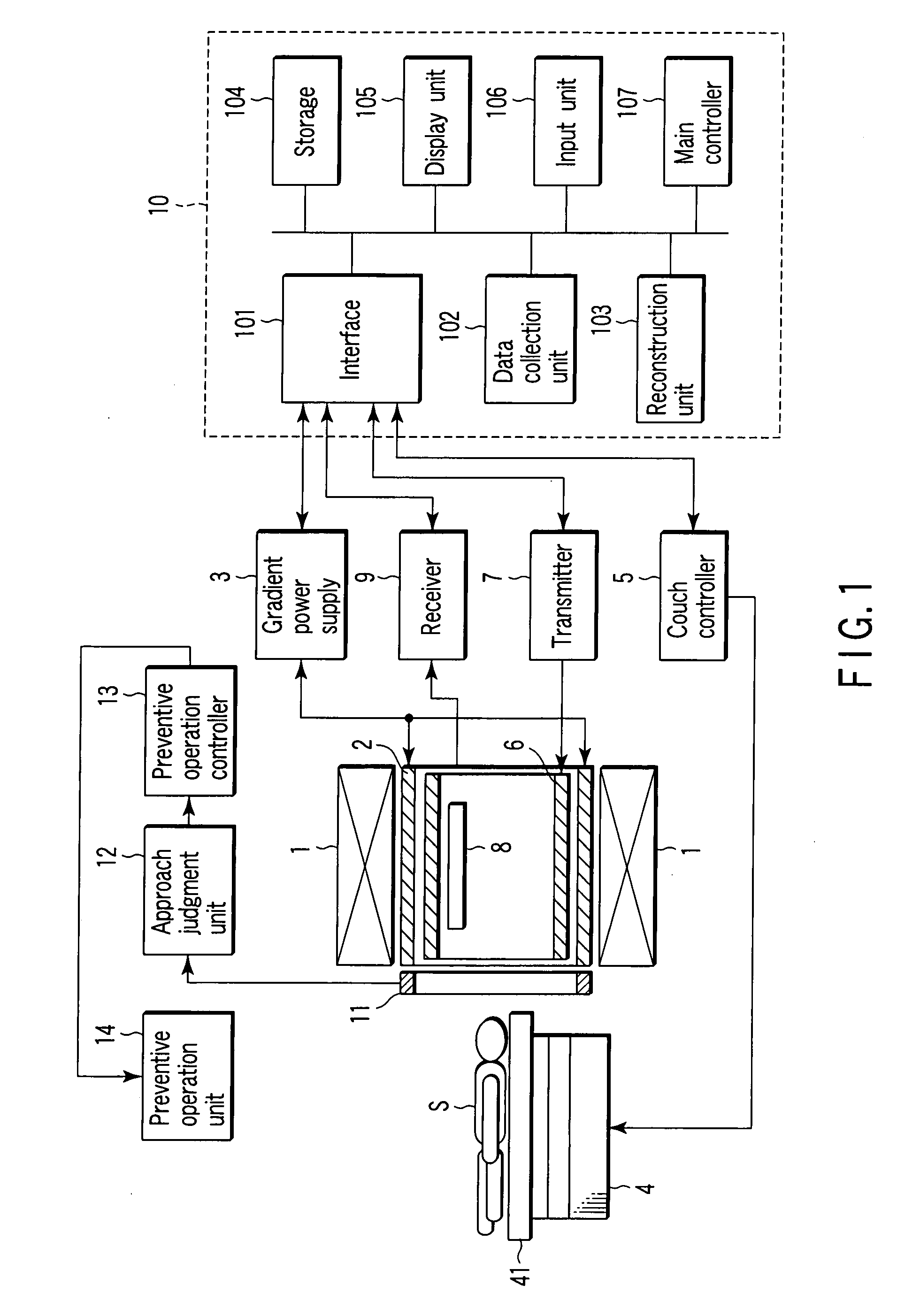
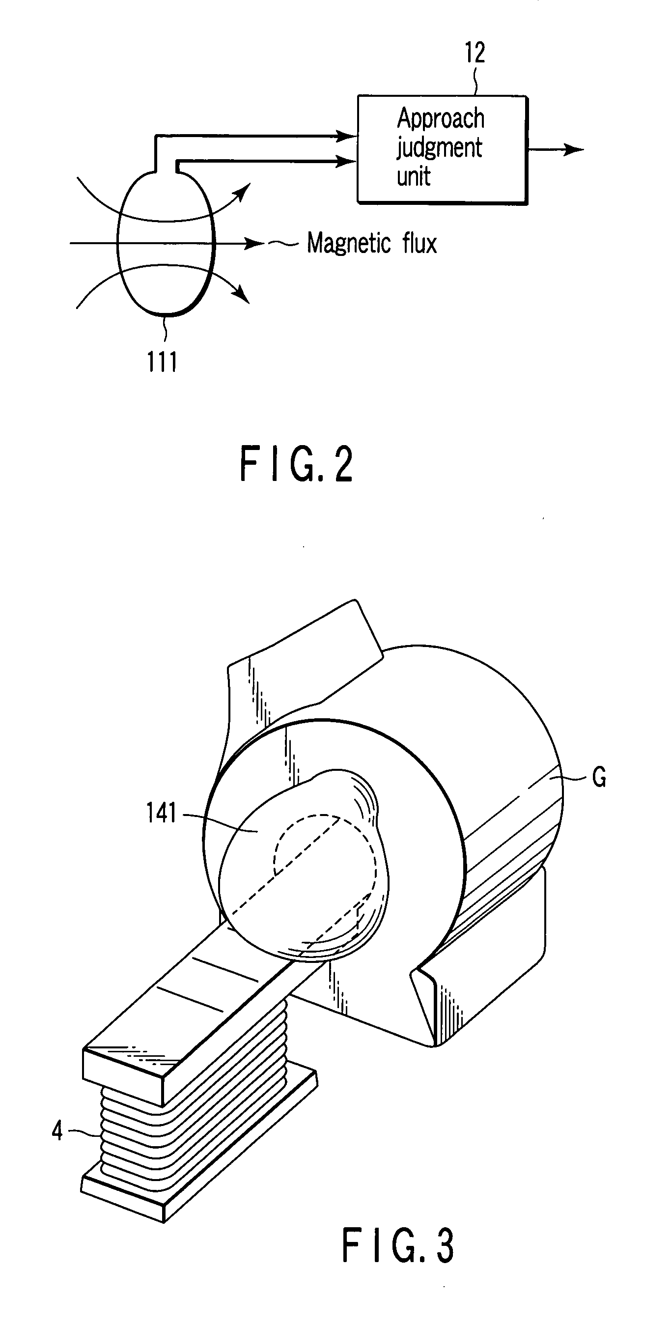
[0024]FIG. 1 is a schematic and block diagram representation of a magnetic resonance imaging apparatus (hereinafter referred to as an MRI apparatus) according to a first embodiment of the present invention. This MRI apparatus shown in FIG. 1 includes a static field magnet 1, a gradient magnetic fieldgradient field coil unit 2, a gradient power supply 3, a couch 4, a couch controller 5, a transmitting RF coil unit 6, a transmitter 7, a receiving RF coil unit 8, a receiver 9, a computer system 10, a detection coil unit 11, an approach judgment unit 12, a preventive operation controller 13, and a preventive operation unit 14.

[0025]The static field magnet 1, which is formed in the shape of a hollow cylinder, generates a uniform static magnetic field in its inside space. As the static field magnet 1 use may be made of, for example, a permanent magnet or a superconducting magnet.

[0026]The gradient magnetic fieldgradient field coil unit 2 is formed in the shape of a hollow cylinder and pla...

second embodiment

[0049]FIG. 5 is a schematic perspective view of a magnetic attraction preventive system according to a second embodiment of the present invention. The magnetic attraction preventive system shown in FIG. 5 includes coil units 21a, 21b, 22a, and 22b, door sensors 23a and 23b, alarm units 24a, 24b, and 24c, and a main unit 25.

[0050]The coil units 21a and 22a, door sensor 23a and alarm unit 24a are each placed in the vicinity of an entrance / exit (hereinafter referred to simply as an entrance) 31a of a front room 31. The coil units 21b and 22b, door sensor 23b and alarm unit 24b are each placed in the vicinity of an entrance 32a of a examination room 32. The alarm unit 24c and main unit 25 are placed in, for example, an operation room (not shown).

[0051]More specifically, the coil units 21a and 22a are placed on the wall or the floor of the front room 31 so as to face each other with the entrance 31a interposed therebetween. The door sensor 23a is mounted on the wall of the front room 31 ...


PUM


Abstract

A magnetic attraction preventive system includes an approach detection unit which generates an approach detection magnetic field and detects the approach of a magnetic material to a magnetic resonance imaging apparatus on the basis of a variation in the strength of the approach detection magnetic field, and a preventive unit which prevents magnetic attraction of the magnetic material to the magnetic resonance imaging apparatus when the approach detection unit detects the approach of the magnetic material to the magnetic resonance imaging apparatus.

Description

CROSS-REFERENCE TO RELATED APPLICATIONS[0001]This application is based upon and claims the benefit of priority from prior Japanese Patent Application No. 2006-100728, filed Mar. 31, 2006, the entire contents of which are incorporated herein by reference.BACKGROUND OF THE INVENTION[0002]1. Field of the Invention[0003]The present invention relates to a magnetic attraction preventive system which prevents magnetic attraction of a magnetic material to a magnetic resonance imaging apparatus which results from a magnetic field generated from the apparatus.[0004]2. Description of the Related Art[0005]A magnetic field generated by a magnetic resonance imaging apparatus extends to the outside of it. For this reason, so-called magnetic attraction can occur in which a magnetic material is attracted to the magnetic resonance imaging apparatus by the magnetic field.[0006]In recent years, the magnetic fields generated by magnetic resonance imaging apparatuses have been much increased in strength....

Claims


Application Information

Patent Timeline
IPC IPC(8): G01R33/28
CPCG01R33/288G01R33/28
Inventor HAYAKAWA, HIROSHI
Owner TOSHIBA MEDICAL SYST CORP
Why Eureka
Try Eureka