
Medical guidance system and control method of medical device

a technology of medical devices and guidance systems, applied in medical science, surgery, diagnostics, etc., can solve the problems of reduced magnetic attraction for driving medical devices, inability to guide medical devices in the intended direction, and reduced controllability of medical devices, so as to improve controllability, stabilize the guide, and increase the drive force of medical devices

Active Publication Date: 2010-03-04
OLYMPUS CORP
View PDF43 Cites 8 Cited by
  • Summary
  • Abstract
  • Description
  • Claims
  • Application Information

AI Technical Summary

Benefits of technology

[0015]In this way, the field direction of the magnetic field exerted on the magnet is controlled based on the displacement. This may prevent the phenomenon in which the medical device is unstably guided due to misalignment between the magnetization direction and the field direction. That is, the displacement is controlled within a predetermined range. This may prevent reduction in magnetic attraction for driving the medical device and reduction in magnetic torque for rotationally driving the medical device. Consequently, the medical device can be stably guided.
[0019]According to this, the field direction of the magnetic field exerted on the magnet is controlled based on not only the displacement, but also at least one of the position and direction of the medical device. Since the magnet is provided in the medical device, the position and the direction of the medical device can be easily converted into the position and the direction of the magnet. Moreover, the field direction of the magnetic field exerted on the magnet may be changed based on the positional relationship between the magnet and the place at which the magnetic field is generated, namely, the magnetic field generation unit. Therefore, the field direction of the magnetic field exerted on the magnet is controlled based on at least one of the position and direction of the medical device. Thereby, the field direction of the magnetic field exerted on the magnet is appropriately controlled compared with a case in which control is not performed based on at least one of the position and direction of the medical device. Consequently, the medical device can be stably guided.
[0035]According to this, the intensity of the magnetic field exerted on the magnet from the outside of a body is changed based on the displacement. Thereby, attraction or torque exerted on the medical device can be controlled, and, consequently, the medical device is stably guided.
[0036]According to the medical guidance system and the control method of a medical device of the invention, the direction of a magnetic field exerted on a magnet is controlled based on displacement being an angle formed between the magnetization direction of the magnet and the direction of a magnetic field applied to the magnet from the outside of a body. Thereby, attraction or torque exerted on a medical device may be controlled, leading to the advantages of increased drive force of the medical device and improvement in controllability thereof.

Problems solved by technology

However, the magnetization direction of the magnet may not correspond to the direction of an applied magnetic field, for example, in the case that a magnet is allowed to generate torque in order to change the direction of a medical device, or in the case that motion of a capsule is restricted due to friction between a medical device and a coeliac tissue, leading to a problem in which the medical device cannot be guided in the intended direction.
However, since the phase around the longitudinal axis of the medical device is not always oriented in the same direction as the direction of the induction field, a phase difference may occur between an actual phase and an estimated phase.
A phase difference will cause a problem of reduction in magnetic attraction for driving the medical device, reduction in magnetic torque for rotationally driving the medical device, or unstable guidance of the medical device.

Method used


Image

  • Medical guidance system and control method of medical device
  • Medical guidance system and control method of medical device
  • Medical guidance system and control method of medical device

Examples


first embodiment

[0071]Hereinafter, a first embodiment of the invention is described with reference to FIGS. 1 to 8.

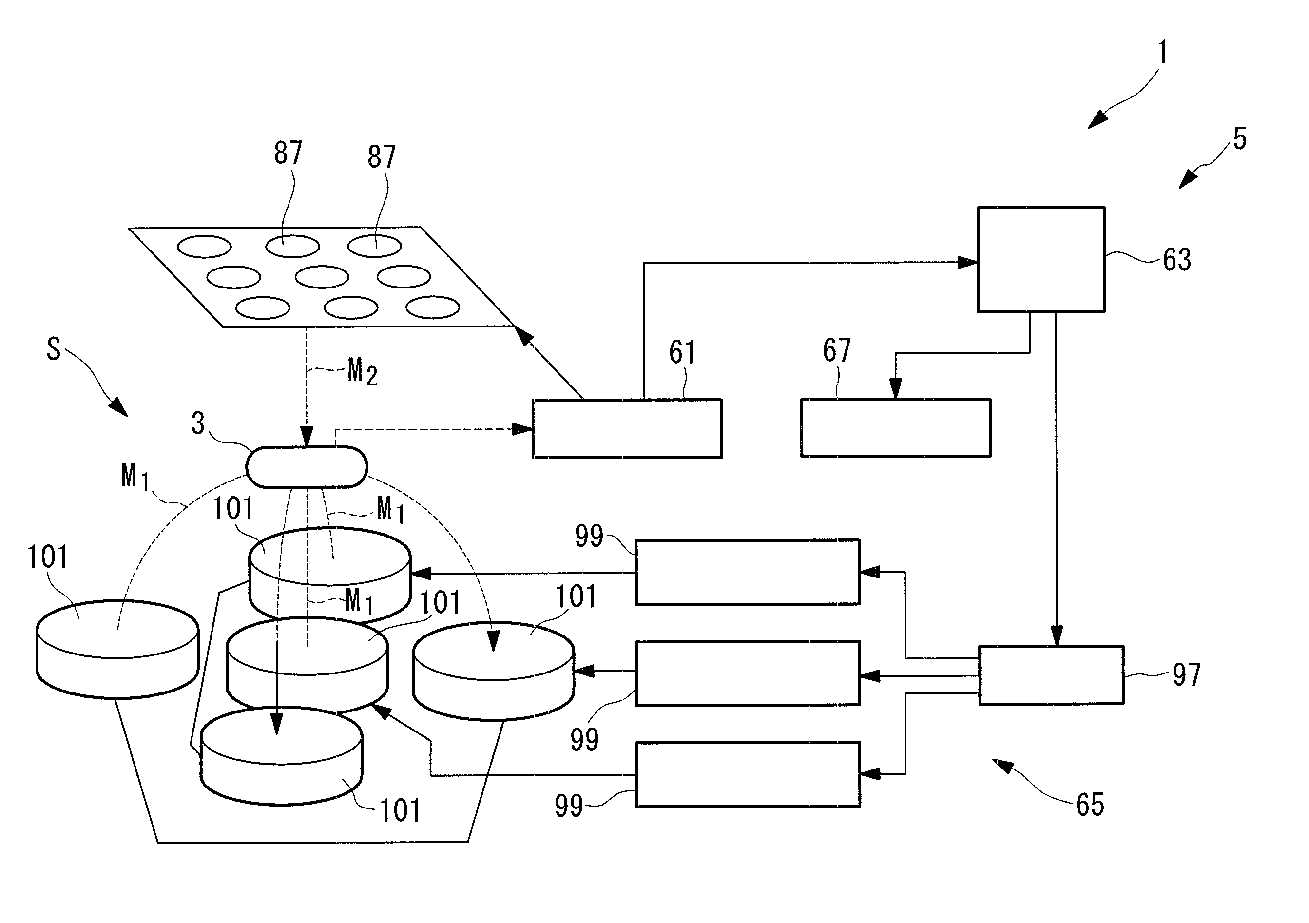
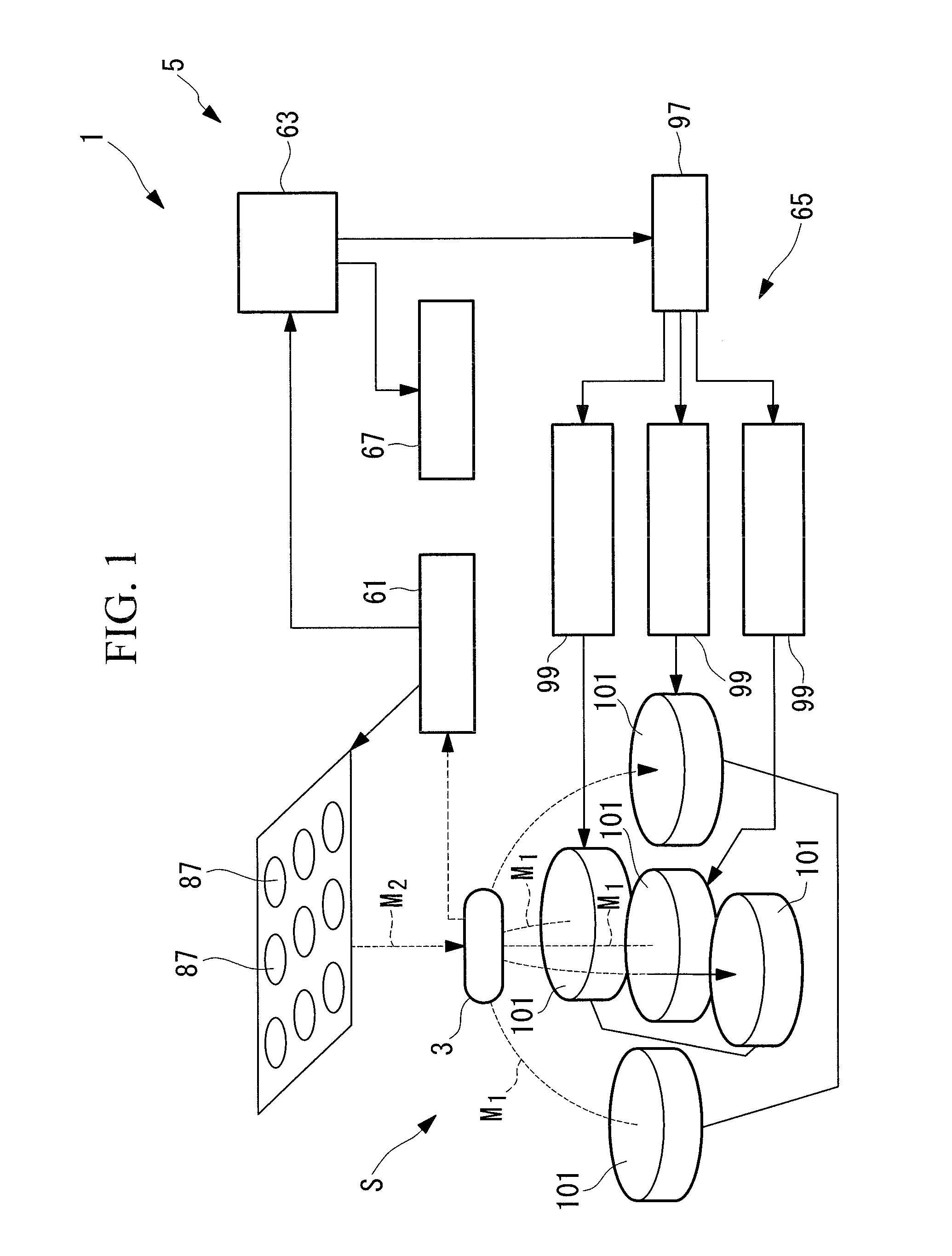
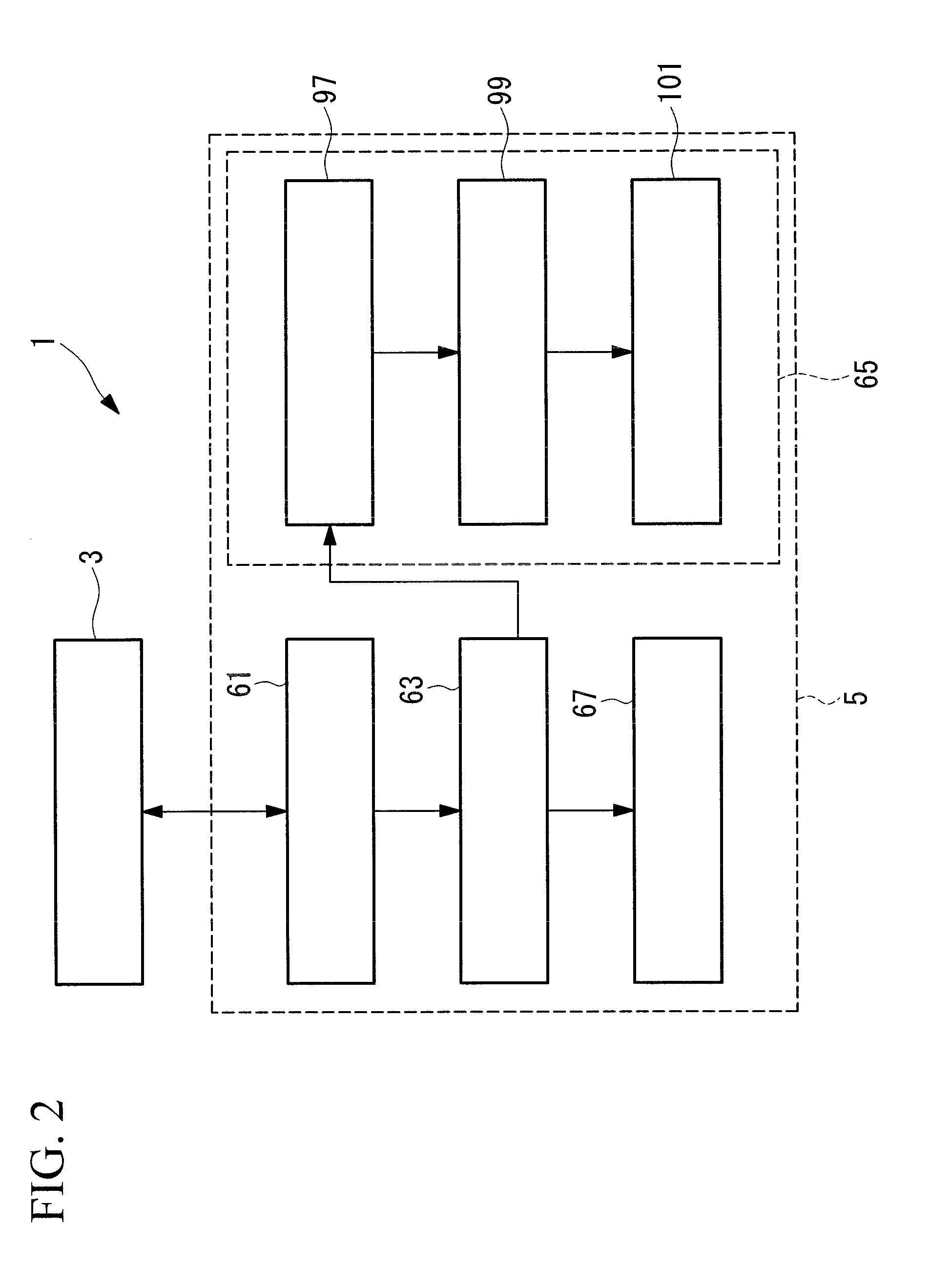
[0072]FIG. 1 shows a general block diagram of a capsule medical device system according to the embodiment, and FIG. 2 shows a block diagram of the capsule medical device system of FIG. 1.

[0073]The capsule medical device system (medical guidance system) 1 according to the embodiment has a capsule medical device 3 to be put into the body cavity of a subject (not shown) and an external device 5 disposed outside the body of the subject as shown in FIGS. 1 and 2.

[0074]FIG. 3 shows a block diagram of the capsule medical device according to the embodiment, and FIG. 4 shows a longitudinal section view of the capsule medical device of FIG. 3.

[0075]As shown in FIGS. 3 and 4, the capsule medical device (medical device) 3 includes a package 7 that stores various devices within the package, an imaging unit (biologic information acquisition unit) 9 that acquires an image (biologic information) of th...

first modification

of First Embodiment

[0178]Next, a first modification of the first embodiment of the invention is described with reference to FIGS. 9 to 11.

[0179]The basic configuration of the capsule medical device system of the modification is the same as that of the first embodiment. However, the system is different from the first embodiment in the detection method of the magnetization direction of the permanent magnet mounted in the capsule medical device. Therefore, in the modification, only particulars regarding the detection method of the guidance field M1 are described with reference to FIGS. 9 to 11, and description of other components and the like are omitted.

[0180]FIG. 9 shows a block diagram of a capsule medical device according to the modification, and FIG. 10 shows a longitudinal section view of the capsule medical device of FIG. 9.

[0181]The same components as in the first embodiment are marked with the same symbols, and descriptions of them are omitted.

[0182]As shown in FIGS. 9 and 10,...

second modification

of First Embodiment

[0190]Next, a second modification of the first embodiment of the invention is described with reference to FIG. 12.

[0191]The basic configuration of the capsule medical device system of the modification is the same as that of the first modification. However, the system is different from the first modification in magnetic field detected by a magnetization direction detection coil. Therefore, in the modification, only the detection method of the magnetization direction of the permanent magnet mounted in the capsule medical device is described using FIG. 12, and descriptions of other components and the like are omitted.

[0192]FIG. 12 shows a block diagram of an external device in a capsule medical device system according to the modification.

[0193]The same components as in the first modification of the first embodiment are marked with the same symbols, and descriptions of them are omitted.

[0194]As shown in FIG. 12, an external device 305 in a capsule medical device syste...


PUM


Abstract

A medical guidance system and a control method of a medical device are provided, which may increase the drive force of a medical device and improve controllability thereof. The medical guidance system has a medical device that includes a biologic information acquisition unit that acquires biologic information of the inside of a body cavity and a magnet that generates drive force in response to a magnetic field exerted from the outside of a body, a magnetic field generation unit 101 that generates the magnetic field to be exerted on the magnet from the outside of a body, and a displacement detection unit 105 that detects displacement being an angle formed between the magnetization direction of the magnet and the field direction of the magnetic field generated by the magnetic field generation unit 101 at the position of the medical device; wherein the magnetic field generation unit 101 is controlled based on the displacement.

Description

TECHNICAL FIELD[0001]The present invention relates to a medical guidance system that guides a medical device inserted into a body cavity, and a control method of the medical device.BACKGROUND ART[0002]As a method of guiding a medical device such as a capsule endoscope within a body cavity, a magnetic guidance technique of a medical device has been developed, in which a magnet is incorporated in the medical device, and a magnetic field is applied to the magnet from the outside, so that the position and the direction of the medical device are controlled (for example, refer to patent citations 1 to 3.[0003]Patent Citation 1: Japanese Unexamined Patent Application, Publication No. 2006-075537[0004]Patent Citation 2: Japanese Unexamined Patent Application, Publication No. 2005-058430[0005]Patent Citation 3: Japanese Unexamined Patent Application, Publication No. 2006-149688DISCLOSURE OF INVENTION[0006]When the guidance control is performed, the magnetization direction of a magnet is desi...

Claims


Application Information

Patent Timeline
IPC IPC(8): A61B1/00
CPCA61B1/00158A61B1/041A61B5/062A61B5/7232A61B5/4839A61B2019/2253A61B5/07A61B34/73
Inventor UCHIYAMA, AKIOCHIBA, ATSUSHIKAWANO, HIRONAO
Owner OLYMPUS CORP
Learn More