
Vehicle Wheel Bearing Apparatus

a technology for bearing apparatus and wheels, which is applied in mechanical apparatus, instruments, transportation and packaging, etc., can solve the problems of reducing detection sensitivity and difficulty in keeping a sufficient radial space, and achieve the effect of reducing sensing ability and sufficient flux density of encoders

Inactive Publication Date: 2008-07-03
NTN CORP
View PDF11 Cites 8 Cited by
  • Summary
  • Abstract
  • Description
  • Claims
  • Application Information

AI Technical Summary

Benefits of technology

The present invention provides a bearing apparatus for a wheel of vehicle that can protect the encoder, improve the sensing ability of the detecting sensor, and prevent penetration of rain water or dust and leak of differential gear oil. The bearing apparatus includes an axle housing, a driving shaft, and a bearing for a wheel. The bearing has an outer member with inner raceway surfaces, an inner member with an inner ring and sealing means for sealing the space between the inner member and the outer member. The bearing also includes a detecting sensor suspended from the axle housing and sealing lips for sealing the detecting sensor. The sealing means includes an annular supporting plate, a pulser ring, and a sealing plate. The sealing plate has a sensor aperture for positioning the detecting sensor. The detecting sensor is inserted through the sensor aperture, which reduces the air gap between the detecting sensor and the encoder and improves sensing ability. The sensor aperture is formed only one in a region near the top of the core member, which prevents the residue of differential gear oil from entering the bearing.

Problems solved by technology

However, in such a bearing apparatus for a wheel of vehicle of the prior art, since the pulse generating ring 71 is arranged such that it radially extends and the signal detection of the detecting sensor 75 is carried out through the cover member 72, it is difficult to ensure sufficient area of the pulse generating ring 71 owing to the limitation of radial space of the bearing and thus the detecting sensitivity is also reduced.
Especially in a vehicle such as a truck having a body of frame structure, it is difficult to keep a sufficient radial space since it requires to use a double row tapered roller bearing having a large load capacity and a wall thickness smaller than that of a double row angular ball bearing.

Method used


Image

  • Vehicle Wheel Bearing Apparatus
  • Vehicle Wheel Bearing Apparatus
  • Vehicle Wheel Bearing Apparatus

Examples


first embodiment

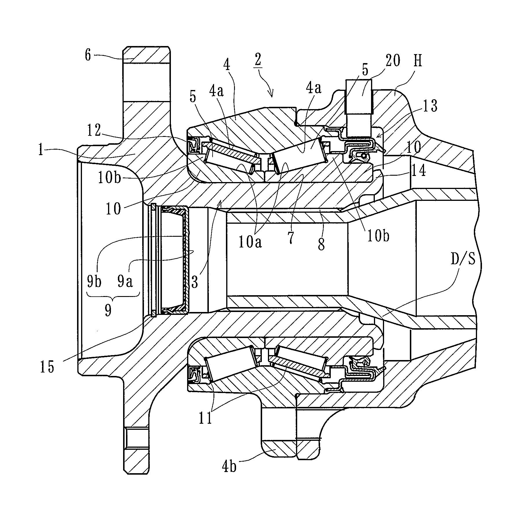
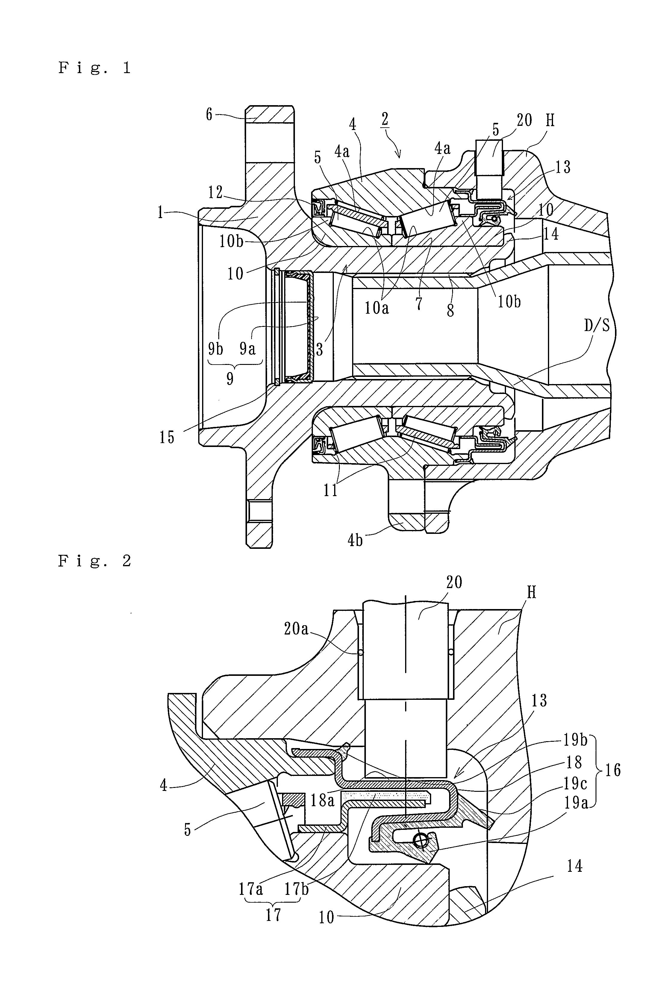
[0029]FIG. 1 is a longitudinal-section view of a first embodiment of a bearing apparatus for a wheel of the present invention, and FIG. 2 is a partially enlarged longitudinal-section view of FIG. 1. In the description of the present invention, a side of a bearing positioned outward a vehicle when it is mounted on a vehicle is referred to as “outboard” side (the left side in a drawing), and a side inward a vehicle is referred to as “inboard” side (the right side in a drawing).

[0030]In a bearing apparatus for a wheel of vehicle of the present invention, a hub wheel 1 and a double row rolling bearing 2 are formed as a unit and connected to a driving shaft “D / S”. The double row rolling bearing 2 comprises an inner member 3, an outer member 4, and a double row rolling elements (tapered rollers) 5 and 5 freely rollably contained between the inner and outer members 3 and 4. The inner member 3 includes the hub wheel 1 and a pair of inner rings 10 and 10 press-fitted onto the hub wheel 1. Th...

second embodiment

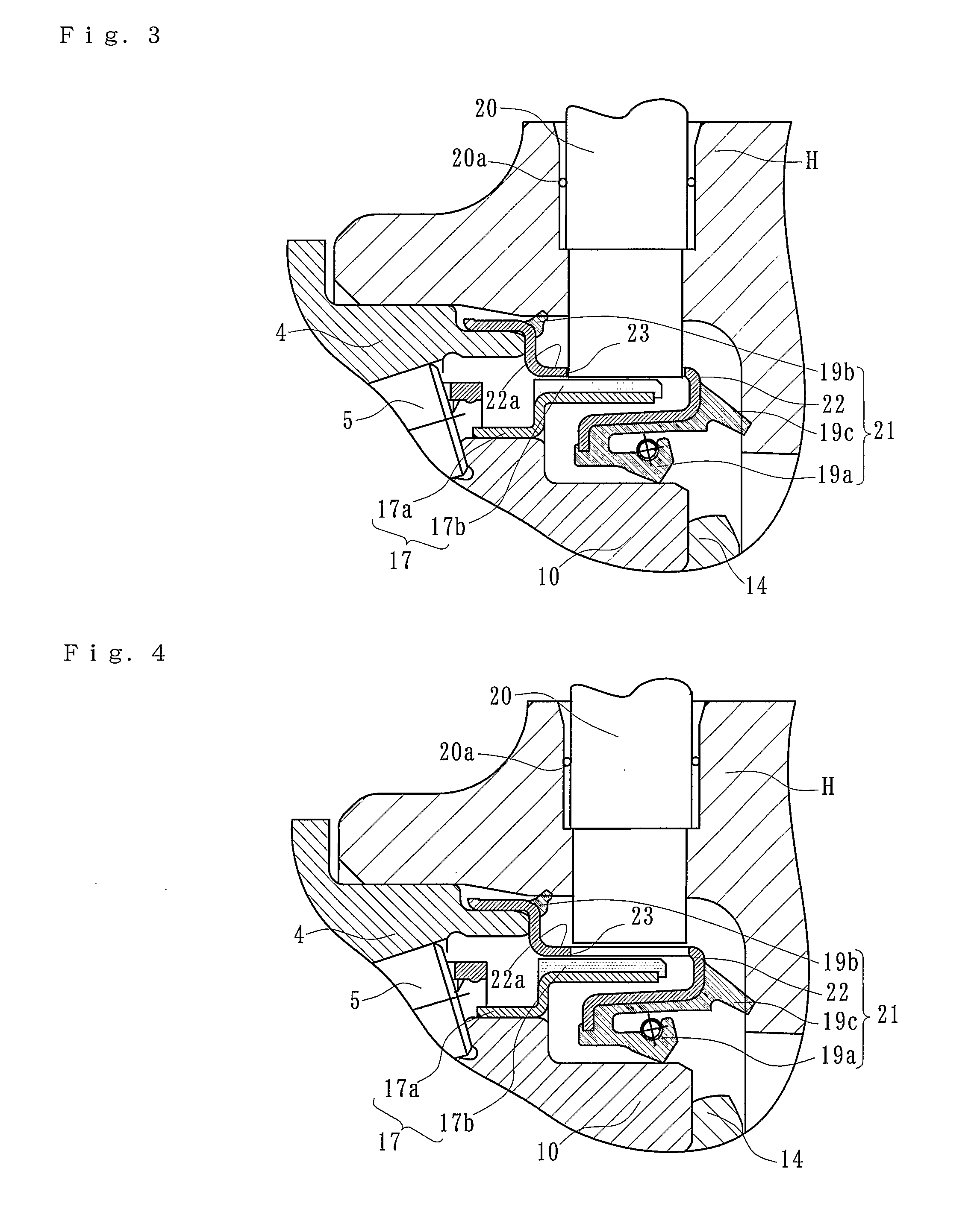
[0041]FIG. 3 shows a second embodiment of the bearing apparatus for a wheel of vehicle of the present invention. Since difference of this embodiment from the first embodiment only resides in the structure of the sealing, same numerals are used as those used in the first embodiment for designating the same structural elements.

[0042]A sealing means 13 of inboard side of this embodiment comprises an annular sealing plate 21 fitted on the outer circumferential surface of one end of the outer member 4, and a pulser ring 17 mounted on the outer circumferential surface of one end of the inner member 10. The sealing plate 21 comprises a core member 22, the radial lip 19a slide-contacting to the outer circumferential surface of the inner ring 10, and sealing lips 19b and 19c contacting to the axle housing “H”. These radial lip 19a and sealing lips 19b and 19c are bonded to the core member 22 via vulcanization.

[0043]The sealing plate 21 is substantially same as the sealing plate 16 except tha...


PUM


Abstract

A vehicle wheel bearing apparatus that protects the encoder, improves the sensing ability of the detecting sensor, prevents penetration of rain water or dust, and prevents leakage of differential gear oil has an inboard side seal (13) with an annular supporting plate (17a) fit onto the outer circumferential surface of one of the inner rings (10). A purser ring (17), having an encoder (17b), is bonded on the outer circumferential surface of the supporting plate (17a). A sealing plate (16), including an annular core member (18 and 22), is fit onto one end of the outer member (4) and covers the cylindrical portion of the encoder (17b). A lip (19a) is bonded on the core member (18 and 22) and is in sliding contact with the inner ring (10). A detecting sensor (20) is suspended from an axle housing “H” and opposes the encoder (17b) via a predetermined radial gap. Sealing lips (18b and 19c) on the sealing plate 16 are arranged between the core member (18 and 22) and the axle housing “H” to seal the detecting sensor (20).

Description

BACKGROUND OF THE INVENTION[0001]1. Field of the Invention[0002]The present invention relates to a bearing apparatus for a wheel of vehicle for rotatably supporting the wheel relative to a suspension apparatus of vehicle, and more particularly to a bearing apparatus for a wheel of vehicle a driving wheel is supported by a double row rolling bearing.[0003]2. Description of Background Art[0004]In a vehicle such as a truck having a body of frame structure, an axle structure of driving wheel of full-floating type has been adopted. Recently, an axle structure in which a double row rolling bearing is united has been adopted in many cases in order to improve the readiness of assembly and to reduce the weight and size thereof. In such a bearing apparatus, it has been known a rolling bearing for a wheel of vehicle having a sealing device integrated with a encoder for detecting the rotation speed of wheel.[0005]For example as shown in FIG. 5, such a bearing apparatus for a wheel of vehicle ha...

Claims


Application Information

Patent Timeline
Patent Type & Authority Applications(United States)
IPC IPC(8): F16C32/00
CPCB60B27/001F16C19/386F16C33/7813F16C33/7886G01P3/487F16C2326/02F16J15/326G01P3/443F16C41/007
Inventor MURANAKA, MASAHIROSOKOLOWSKY, DETLEFNULLMEIER, DANIEL
Owner NTN CORP
Learn More