Eureka AIR delivers breakthrough ideas for toughest innovation challenges, trusted by R&D personnel around the world.

Ballistic resistant antenna assembly

Active Publication Date: 2008-05-29
THE BOEING CO
View PDF12 Cites 8 Cited by
  • Summary
  • Abstract
  • Description
  • Claims
  • Application Information

AI Technical Summary

Benefits of technology

[0009]An advantage of the present disclosure is that the antenna according to the present disclosure is capable of withstanding a Department of Justice Level IV ballistic threat, while maintaining communication via transmission of electromagnetic energy.
[0010]Another advantage of the present disclosure is that vehicles equipped with ballistic resistant communication systems according to an embodiment of the present disclosure allow continuous communication, while vehicles are operating in hostile environments subject to ballistic threats. Further, the ability of the communication and / or radar system to absorb heavy fire from close-in threats while maintaining electronic communication and radar functions increases the likelihood that the threat can be identified and / or eliminated.
[0011]Still another advantage of an embodiment of the present disclosure includes the ability to utilize sensors that allow a vehicle to electro-magnetically sense the current terrain, road conditions or other conditions present underneath the vehicle.

Problems solved by technology

Such vehicles are typically in harsh, adverse and violent environments where ballistic protection is essential to the vehicle survival.
The current urban environment warfare requires a large amount of close-in combat.
However, antennas for use with communication systems for use on such vehicles suffer from the drawback that in order to send and receive the electromagnetic energy from the desired directions, the antennas are typically fabricated from materials and are mounted in locations that are vulnerable to ballistic threats.
However, protective shields capable of providing protection from ballistic threats are generally not transparent or permeable to the operating electromagnetic frequencies of most antennas.
Therefore, currently no antenna system exists that provides antennas capable of emitting and / or receiving electromagnetic energy while remaining resistant to ballistic attack.
However, such metallic barriers retard transmission of electromagnetic energy, making communicating or sensing, either electrically, optically, thermally or with some other electromagnetic phenomena, through this protective barrier difficult or impossible.
Therefore, antennas currently available are substantially unprotected from ballistic attack.

Method used


Image

  • Ballistic resistant antenna assembly
  • Ballistic resistant antenna assembly
  • Ballistic resistant antenna assembly

Examples


Embodiment Construction

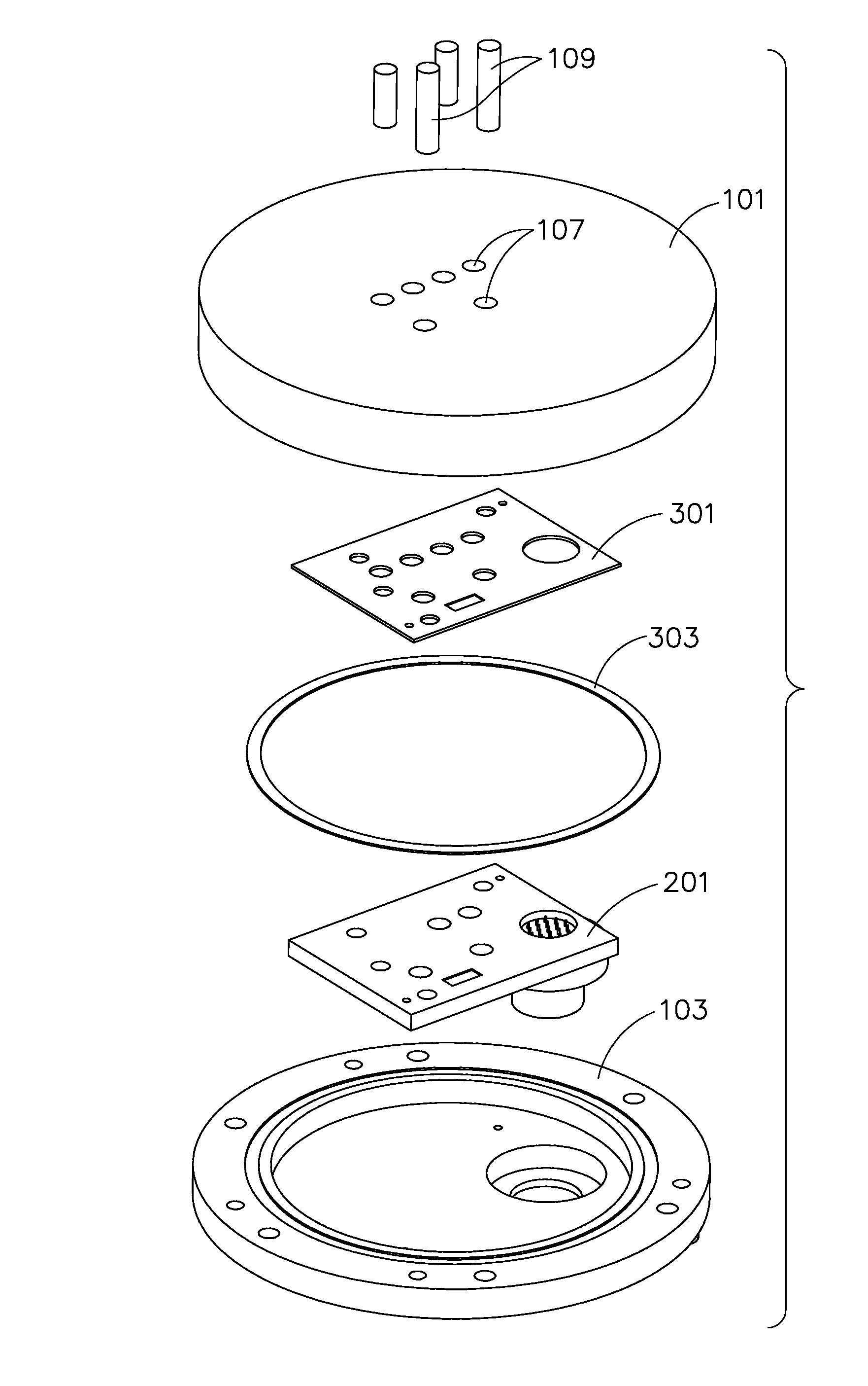
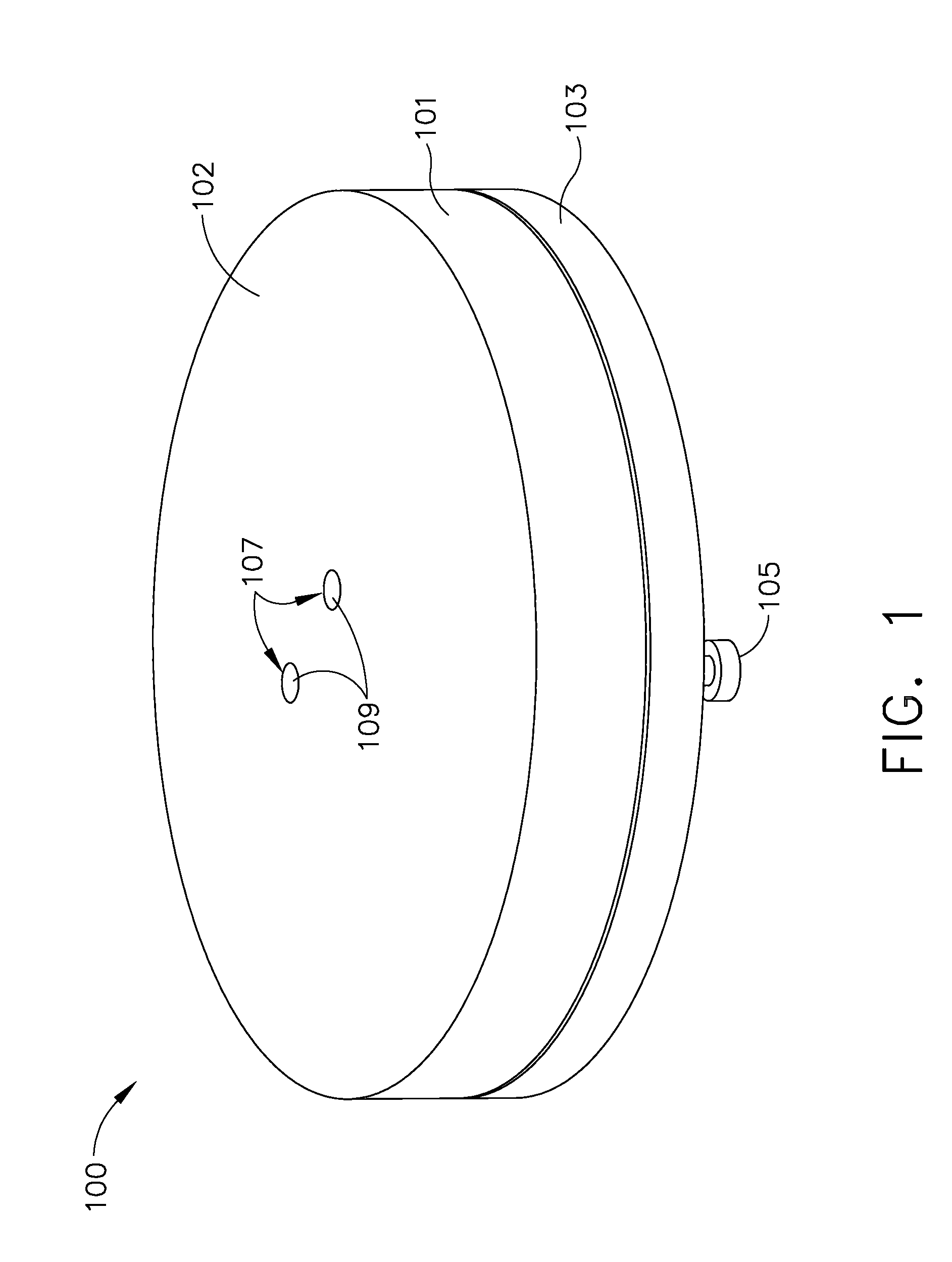
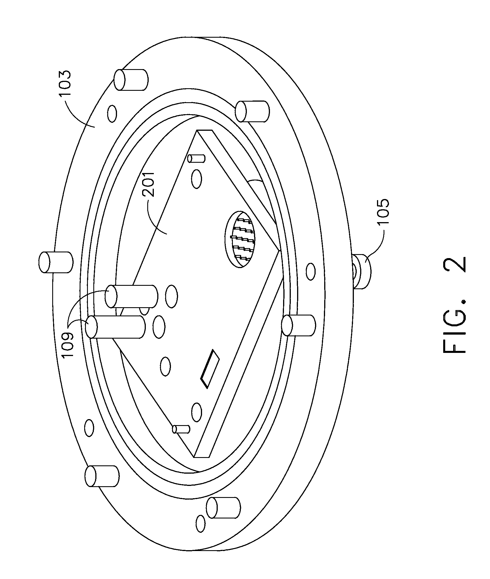
[0024]The present disclosure is directed to a ballistic resistant communication system having an antenna utilizing ballistic resistant material. Communication system, as used herein include systems that utilize electromagnetic energy either emitted or received to communicate or sense conditions. Examples of communications systems include, but are not limited to radar systems, broadband communications systems, and radio frequency (RF) sensor systems. The wavelengths of electromagnetic energy usable with the present disclosure are not particularly limited and may include any wavelength usable as a communication, sensing or radar application. Suitable wavelengths for use with the present disclosure may include, but is not limited to super high frequency (i.e., 3-30 GHz), Ku band, (i.e., 12-18 GHz), or any other frequency, such as Q-band, K-band, KA-band, and X-band, usable for communications or sensing applications.

[0025]Ballistic resistant material and material resistant to ballistic ...


PUM

PropertyMeasurementUnit
Areaaaaaaaaaaa
Wavelengthaaaaaaaaaa
Energyaaaaaaaaaa

Abstract

A ballistic resistant antenna for use with a ballistic resistant communications system having a first plate fabricated from a ballistic material. The first plate has at least one opening configured to allow transmission of electromagnetic energy at a predetermined range of electromagnetic wavelengths. The antenna also has at least one plug having a geometry that is capable of insertion into the at least one opening. The at least one plug is made up of a material that is substantially transparent to the predetermined range of electromagnetic wavelengths.

Description

STATEMENT REGARDING FEDERALLY SPONSORED RESEARCH OR DEVELOPMENT[0001]This invention was made with Government support under Contract #JUYS05001 awarded by U.S. Army. The Government has certain rights in this invention.FIELD OF THE INVENTION[0002]The present disclosure is directed to antenna assemblies. In particular, the present disclosure is directed to antenna assemblies having a ballistic resistant structure.BACKGROUND OF THE INVENTION[0003]Antennas find use in a variety of applications, including those applications subject to ballistic impact, such as in military vehicles. Such vehicles are typically in harsh, adverse and violent environments where ballistic protection is essential to the vehicle survival. Antennas may emit or receive electromagnetic energy, for example, for the purposes of communication. The current urban environment warfare requires a large amount of close-in combat. Electro-optical / electromagnetic data links, radar and other electromagnetic sensors are sensiti...

Claims


Application Information

Patent Timeline
IPC IPC(8): H01Q1/42H01P11/00
CPCY10T29/49016H01Q1/002
Inventor NAVARRO, JULIO A.BOSTWICK, RICHARD N.LAQUER, ANDREW G.
Owner THE BOEING CO
Why Eureka
Eureka Blog
Learn More