Optical Projection System and Projection Device Having the Same
- Summary
- Abstract
- Description
- Claims
- Application Information
AI Technical Summary
Benefits of technology
Problems solved by technology
Method used
Image
Examples
first example
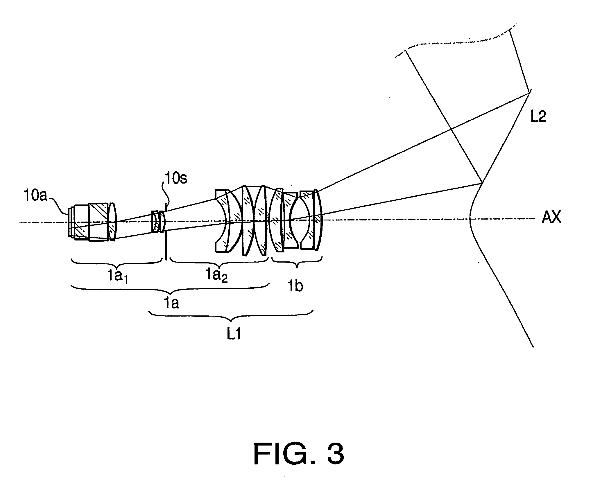
[0077]FIG. 5 shows a lens arrangement of the first optical system L1 of the optical projection system 10 according to the first example. Table 1 shows numeric specifications of the optical projection system 10 according to the first example.
TABLE 1SurfaceNo.rdndνd1∞3.001.5688356.42∞1.003∞15.001.5688356.44∞0.505∞19.001.7015441.26∞0.50770.5467.611.7432049.38−73.20437.939−188.4892.411.4970081.510−49.0561.7711−24.4792.501.6989530.112−59.2320.2013884.2956.151.4970081.514−32.46763.5415−32.6652.001.6398034.516−216.78313.191.6516058.517−47.1020.20181611.24311.401.7129953.919−89.9440.2020100.54212.251.7725049.621−361.1052.312281.02612.001.8051825.423177.3834.7624−345.8984.001.7725049.62543.11320.2726−39.8294.001.7725049.627930.6471.4628−1419.8077.001.4917657.429−99.702152.763041.068—
[0078]In Table 1 (and on the following similar Tables), “r” denotes the curvature radius (mm) of each optical surface, “d” denotes the distance (mm) from each optical surface to the next optical surface of the le...
second example
[0082]FIG. 7 shows a lens arrangement of the first optical system L1 of the optical projection system 10 according to the second example. Table 3 shows numeric specifications of the optical projection system 10 according to the second example.
TABLE 3SurfaceNo.rdndνd1∞3.001.5688356.42∞1.003∞12.001.4874970.24∞15.055123.2267.511.7432049.36−55.33318.91749.1854.511.4970081.58−214.8611.999−55.2522.501.6034238.01027.9104.051132.80811.301.4970081.512−47.88856.6013−24.1652.001.6476933.814−604.77613.181.6516058.515−38.7370.2016−234.8737.801.7129953.917−68.8390.2018116.93810.401.7725049.619−188.59414.752095.38912.001.8051825.421497.1251.8722−581.6134.001.7725049.62346.09116.2324−37.5724.001.7725049.625−2752.4241.002625904.1537.001.4917657.427−120.281185.142850.752—
[0083]In Table 3, surfaces Nos. 1 to 12 belong to the lens group 1a1, surfaces Nos. 13 to 19 belong to the lens group 1a2, surfaces Nos. 20 to 27 belong to the second lens group 1b, and surface No. 28 belongs to the second optical sy...
third example
[0086]FIG. 9 shows a lens arrangement of the first optical system L1 of the optical projection system 10 according to the third example. Table 5 shows numeric specifications of the optical projection system 10 according to the third example.
TABLE 5SurfaceNo.rdndνd1∞1.001.5163364.12∞1.003∞25.001.7015441.24∞0.505∞30.001.7015441.26∞0.50751.5278.481.7432049.38−149.23236.589−201.1422.561.4970081.510−54.2692.0011−27.0952.501.6989530.112−66.8120.2013−511.2393.481.4970081.514−35.64479.7715−36.1022.001.6398034.516−141.84213.071.6516058.517−50.9080.2018−524.68011.421.7129953.919−87.3250.2020105.85614.651.7725049.621−315.0110.2022101.40511.091.8051825.423293.7525.1324−309.5934.001.7725049.62551.19421.4826−53.3604.001.7725049.627−117.3965.5028−63.6767.001.4917657.429−149.950145.883039.875—
[0087]In Table 5, surfaces Nos. 1 to 14 belong to the lens group 1a1, surfaces Nos. 15 to 21 belong to the lens group 1a2, surfaces Nos. 22 to 29 belong to the second lens group 1b, and surface No. 30 belongs ...
PUM
 Abstract
Description
Claims
Application Information
 - R&D
- Intellectual Property
- Life Sciences
- Materials
- Tech Scout
- Unparalleled Data Quality
- Higher Quality Content
- 60% Fewer Hallucinations
Browse by: Latest US Patents, China's latest patents, Technical Efficacy Thesaurus, Application Domain, Technology Topic, Popular Technical Reports.
© 2025 PatSnap. All rights reserved.Legal|Privacy policy|Modern Slavery Act Transparency Statement|Sitemap|About US| Contact US: help@patsnap.com


