Multiple-board power converter

a power converter and multi-board technology, applied in the direction of printed circuit aspects, electrical apparatus construction details, stacked spaced pcbs, etc., can solve the problems of reducing the available board area for mounting components, and reducing the thermal isolation of sensitive components

Active Publication Date: 2008-05-29
TDK LAMBDA CORP
View PDF13 Cites 16 Cited by
  • Summary
  • Abstract
  • Description
  • Claims
  • Application Information

AI Technical Summary

Benefits of technology

[0007]The present invention provides a DC-DC power converter that comprises two or more Printed Wiring Boards (PWB) mounted parallel to one another and without encapsulation. Electronic components can be mounted on both sides of each board. The open design and parallel orientation of the PWBs allow airflow over components mounted on the PWBs. The PWBs are preferable made of FR-4 with copper foils, with one thicker board being comprised of more copper layers and the other boards comprised of less copper layers. In the preferred embodiment, the power processing elements are housed in the thicker PWB, while the thinner boards house the control circuitry.

Problems solved by technology

The main limitation of this configuration is the limited available board areas for mounting components.
Furthermore, it does not provide thermal isolation of sensitive components and is subject to noise from the power elements.
Furthermore, components often have to be shrunk to fit the available footprint, which reduces the upper power range, e.g., ˜50 W for a 1″×1″ footprint.
However, the “daughter” boards are not parallel to the main board, which can interfere with airflow over the components depending on the orientation of the power converter.
Many current designs also have many interconnects between the boards, which reduces the board area available for mounting components.

Method used


Image

  • Multiple-board power converter
  • Multiple-board power converter
  • Multiple-board power converter

Examples


Embodiment Construction

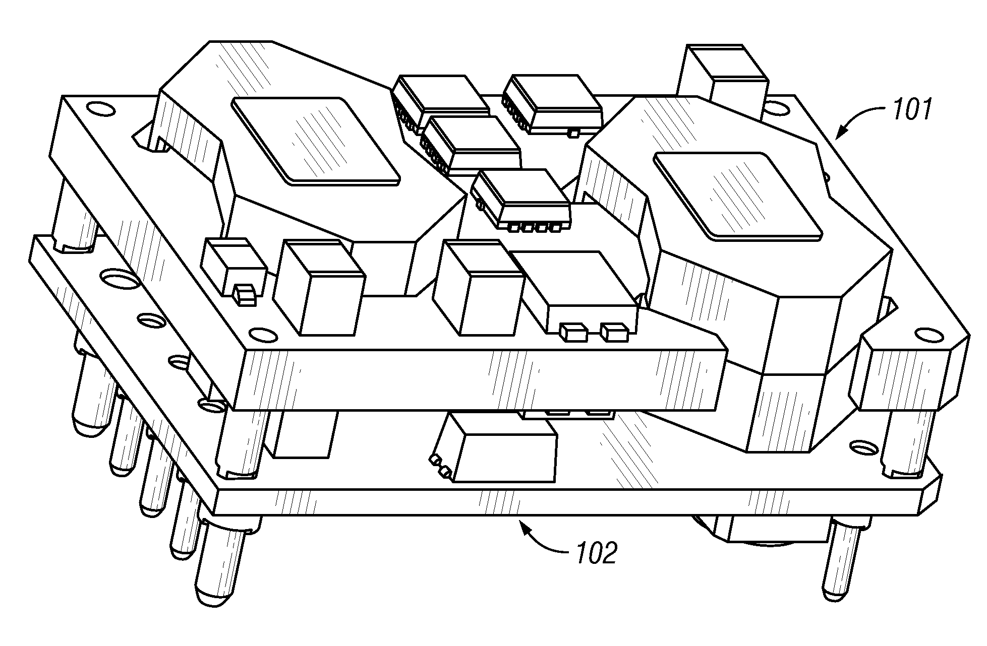
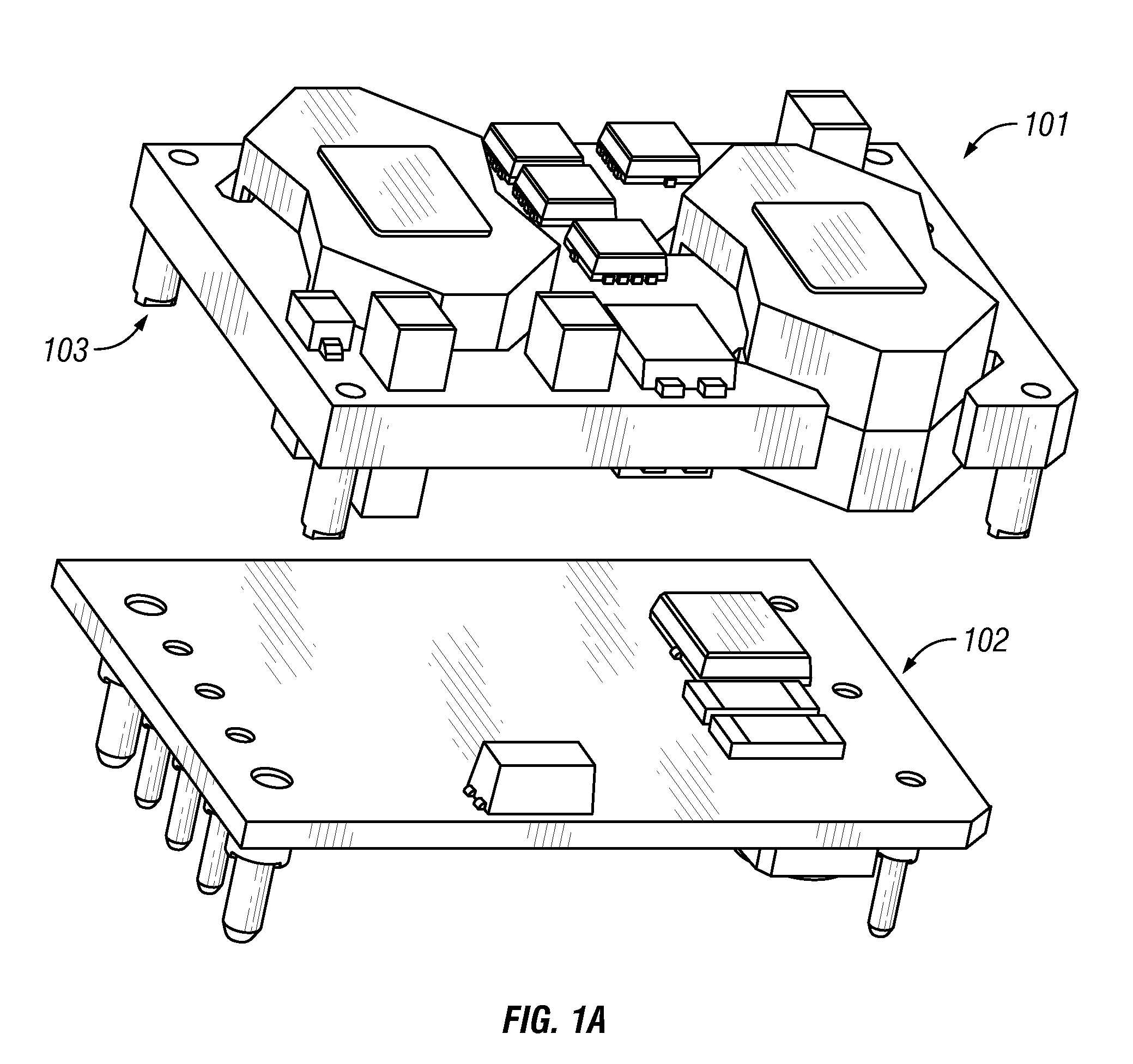
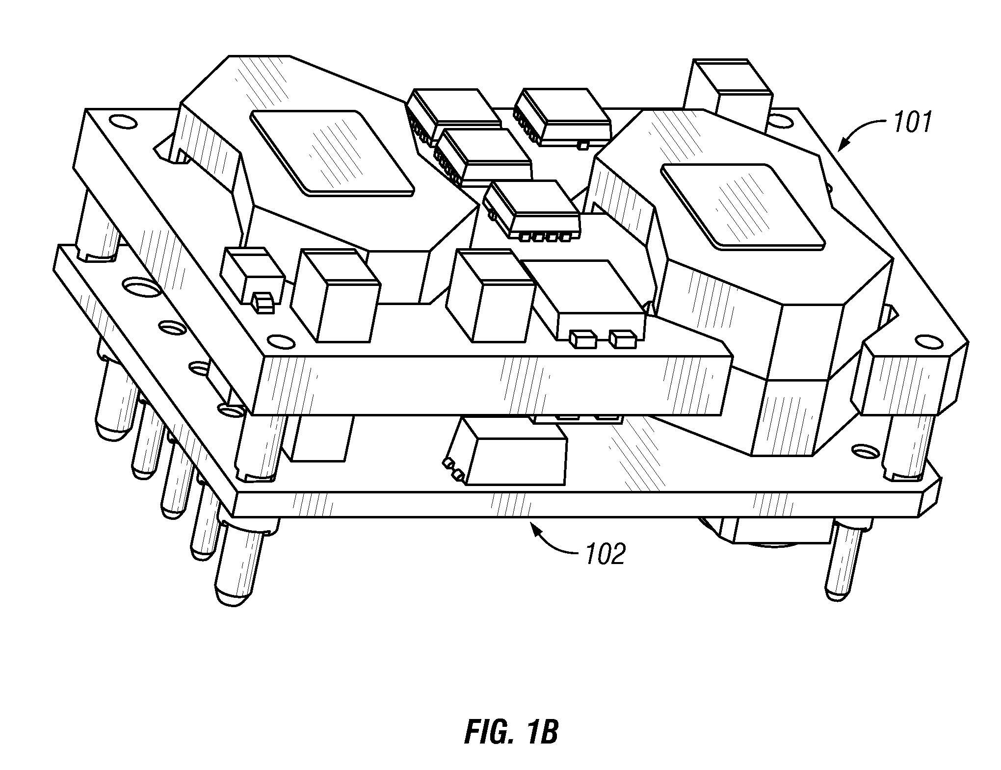
[0017]FIG. 1A shows a top perspective exploded view of a DC-DC power converter in accordance with a preferred embodiment of the present invention. FIG. 1B is a top perspective view of the assembled power converter. For ease of illustration, the example power converter shown in the figures comprises two multi-layer Printed Wiring Boards 101, 102 parallel to each other, connected by several interconnect pins. However, it should be emphasized that the present invention is not limited to two PWBs in parallel.

[0018]The open frame design allows airflow between the boards, increasing the surface area available for mounting components, and the parallel configuration allows fresh airflow to cool components regardless of the orientation of the power converter.

[0019]FIG. 1C is a bottom perspective exploded view of the power converter, and FIG. 1D is a bottom perspective view of the assembled power converter. As can be seen in FIGS. 1A-1D, unlike prior art power converter configurations, the pr...


PUM


Abstract

The present invention provides a DC-DC power converter that comprises two or more Printed Wiring Boards (PWB) mounted parallel to one another and without encapsulation. Electronic components can be mounted on both sides of each board. The open design and parallel orientation of the PWBs allow airflow over components mounted on the PWBs. The PWBs are preferable made of FR-4 with copper foils, with one thicker board being comprised of more copper layers and the other boards comprised of less copper layers. In the preferred embodiment, the power processing elements are housed in the thicker PWB, while the thinner boards house the control circuitry.

Description

TECHNICAL FIELD[0001]The present invention relates generally to power converters, and more specifically to a power converter comprises two or more printed wiring boards in parallel.BACKGROUND OF THE INVENTION[0002]DC-to-DC converters are common components that take a first input voltage and convert it into one or more output voltages. This allows a user to take a higher battery voltage, such as 48 volts, and convert it down to a first and second output voltage, such as 12 volts and 5 volts, enabling the higher voltage DC source to be used to power various circuits that require lower voltage. Such a converter can provide either a single output voltage or multiple voltage outputs. DC-DC power converters typically comprise one of three configurations.[0003]The first configuration is a single FR-4 Printed Wiring Board (PWB) with parts on both sides, with or without encapsulation. Flame Resistant 4 (FR-4 ) is a form of epoxy resin bonded glass fabric (ERBGF). The main limitation of this ...

Claims


Application Information

Patent Timeline
Patent Type & Authority Applications(United States)
IPC IPC(8): H01R12/16
CPCH02M3/00H05K1/144H05K1/182H05K2201/10318H05K2201/042H05K2201/1003H05K2201/10303H05K7/1092H02M3/003
Inventor CHENG, SUN-WEN CYRUSWILDRICK, CARL MILTONBOYLAN, JEFFREY JOHN
Owner TDK LAMBDA CORP
Why Eureka
Try Eureka