Identification device for visually identifying cables or ducts over their entire length

a technology of visual identification and identification device, which is applied in the direction of non-rotary current collectors, geological measurements, rotary current collectors, etc., can solve the problems of human error risk, inability to apply a method in the case of cables or ducts having portions that are manually or visually, and inability to accurately identify cables. , to achieve the effect of facilitating its passage in cramped spaces and without the risk of catching

Inactive Publication Date: 2008-05-29
BRUNET
View PDF4 Cites 14 Cited by
  • Summary
  • Abstract
  • Description
  • Claims
  • Application Information

AI Technical Summary

Benefits of technology

[0011]The disclosure aims to remedy the abovementioned drawbacks, and thus an exemplary embodiment provides a device for identifying cables or ducts which, while still being of simple and inexpensive design, allows visual identification not only of the end but also the entire path of a cable or duct, even if another end of the cable or duct is not directly accessible, and to do so without requiring high power levels.
[0014]Thus, an exemplary embodiment of the disclosure adds adding one or more electroluminescent wires to a cable or duct, which wires extend over the entire length of the cable or duct, thereby allowing the operator to display, in a continuous manner, the path of the cable or duct thanks to the illumination of the electroluminescent wire(s), either from an accessible end or possibly from any point along the length of the cable or duct. One particular advantage of an exemplary embodiment of the device is the possibility of illumination over a very great length, possibly up to several hundred metres, using a single electroluminescent wire and from a single power supply point.
[0021]In particular, connection means for supplying power to the electroluminescent wire may be placed near each of the ends of the cable or duct. These connection means thus make it possible to inject the electric current at an already identified and accessible end of the cable or duct and to trace the cable or duct from this end over its entire length.
[0023]Advantageously, the connection means for supplying power to the electroluminescent wire are made in the form of a power connector fixed to said electroluminescent wire and surrounding the cable or duct, this power connector being designed to cooperate with a power injector formed from two opposed half-shells, which include internal electrical contacts, the two half-shells being able to be closed up so as to grip the cable or duct. Such an injector for supplying power to the electroluminescent wire may be brought in over the top of the cable or duct, without it being necessary to interrupt this cable or duct by cutting or disconnecting it. Advantageously, the power connector has a spherical general shape, while the power injector comprises two hemispherical half-shells, thereby facilitating its passage in cramped spaces, without the risk of catching.

Problems solved by technology

In the various technical fields mentioned above, the problem that commonly arises is how to identify and / or trace cables or ducts, either to identify a cable or duct from an assembly comprising a relatively large number of cables or ducts or simply to determine the path of a single cable or duct.
A first method consists quite simply in manually or visually following the continuous path of a cable or duct, with risks of human error due to the difficulty of tracing a cable or duct when it lies within a multitude of other cables or ducts of similar appearance.
In addition, this method cannot be applied in the case of cables or ducts having portions that are manually or visually inaccessible, for example, cables or ducts passing through false floors or false ceilings.
This technique does not allow precise identification of a cable when it lies within other contiguous cables.
In addition, it is a technique that sometimes requires the normal operation of the cable to be interrupted and which in certain cases cannot be applied, for example for ducts made of an electrically non-conducting plastic, for example optical patch cords.
However, owing to the power levels needed to illuminate optical fibres over their entire length, such a method is in practice limited to the illumination of one end of the fibre, when light is injected into its other end.
However, the solutions considered here are not appropriate for tracing and identifying the entire path of a cable or duct since they only make it possible to identify one end of the cable or duct.
Moreover, these solutions are unreliable, or even inapplicable, if the operator does not know where to look for the other end of the cable or duct.

Method used


Image

  • Identification device for visually identifying cables or ducts over their entire length
  • Identification device for visually identifying cables or ducts over their entire length
  • Identification device for visually identifying cables or ducts over their entire length

Examples


Embodiment Construction

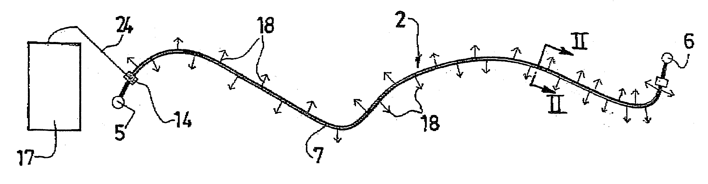
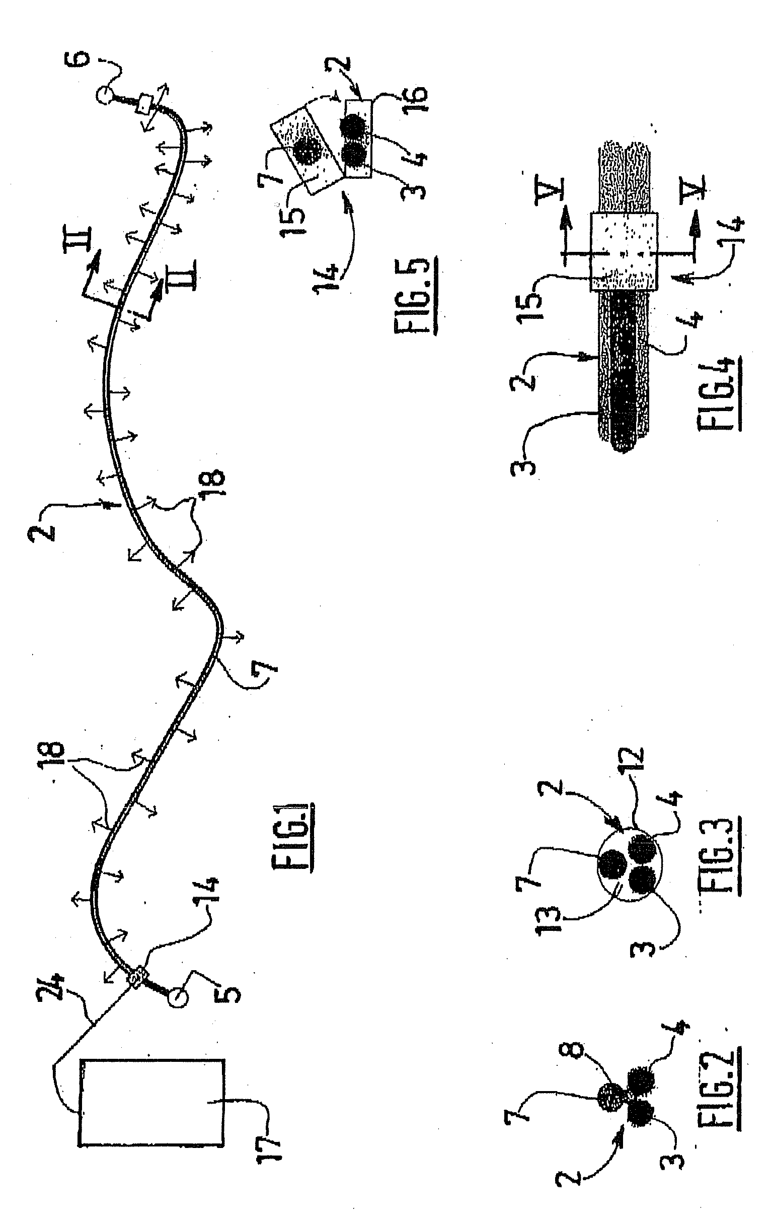
[0041]Referring firstly to FIGS. 1 to 5, the identification device is shown, as an example of its application, in combination with an optical patch cord, that is to say a cord denoted overall by the numerical reference 2, which joins two parallel optical fibres 3 and 4. The two ends of the cord 2 have optical connectors 5 and 6, that are known per se and not detailed here.

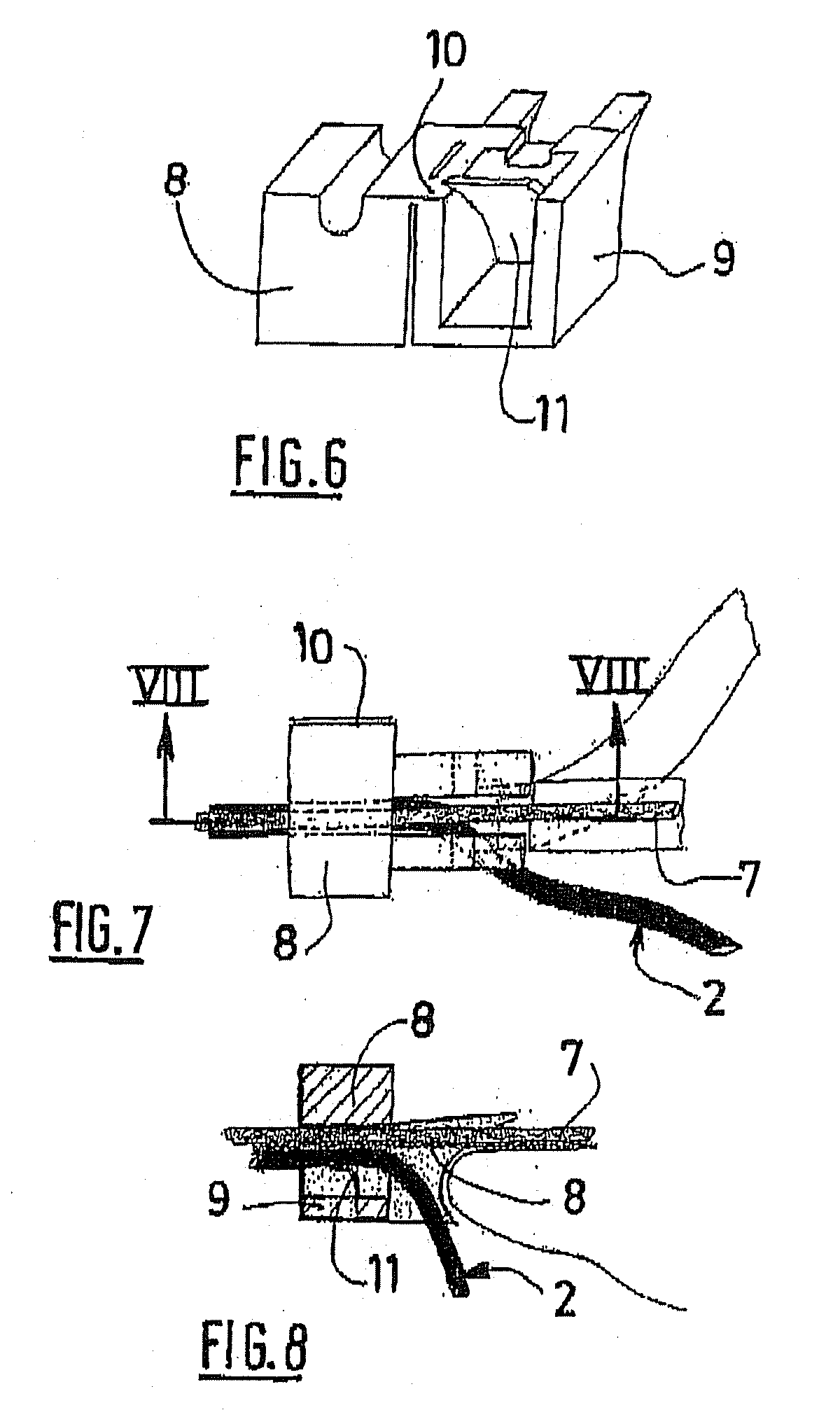
[0042]The identification device, associated with the cord 2, mainly comprises an electroluminescent wire 7 that extends along the cord 2, practically from one end of this cord 2 to the other, to which it is fastened by means that will be described below.

[0043]As regards the electroluminescent wire 7 itself, this is a product known per se, and especially one used hitherto for decorative purposes, which includes a central electrical conductor or “core” that is covered with a phosphor-based layer having electroluminescent properties. Said layer is itself surrounded by at least one other outer electrical conductor woun...


PUM


Abstract

The identification device comprises at least one electroluminescent wire that extends along the cable or duct to be identified. The electroluminescent wire is designed to be electrically supplied in a temporary manner, so as to display the path of the cable or duct. This device is applicable to the identification of electrical cables, or pneumatic and hydraulic ducts, or fibre-optic cables or cords.

Description

TECHNICAL FIELD OF THE INVENTION[0001]The disclosure relates to a device intended for visually identifying cables or ducts, this device having applications in the electrical field, data-processing field, etc. as regards cables, and also in the pneumatic and hydraulic fields as regards ducts. The term “cable” covers here electrical wires and cables of any length and of any size, conveying signals or transporting electrical energy, and also fibre-optic cables such as those referred to as optical “patch cords” (or “jumpers”).DESCRIPTION OF THE RELATED ART[0002]In the various technical fields mentioned above, the problem that commonly arises is how to identify and / or trace cables or ducts, either to identify a cable or duct from an assembly comprising a relatively large number of cables or ducts or simply to determine the path of a single cable or duct. For example, it may be required to identify and trace a data-processing “patch” cord intermingled with numerous other similar cords in ...

Claims


Application Information

Patent Timeline
Patent Type & Authority Applications(United States)
IPC IPC(8): F21V9/16
CPCG01V15/00H01B7/36
Inventor BRUNET, PATRICE
Owner BRUNET
Why Eureka
Try Eureka