Medical Monitoring System

a monitoring system and medical technology, applied in the field of medical monitoring systems, can solve the problems of reducing the fidelity of replayed data, affecting the analysis of recorded signals, and suffering loss of fidelity of recorded data, so as to achieve better descriptors of behaviour and predictive capabilities

Inactive Publication Date: 2008-05-29
QUEENSLAND THE UNIV OF
View PDF3 Cites 7 Cited by
  • Summary
  • Abstract
  • Description
  • Claims
  • Application Information

AI Technical Summary

Problems solved by technology

Due to the limitations in memory size, it is commonplace to compress such data and consequently suffer loss in fidelity of that which is recorded.
This is time consuming and can also reduce the fidelity of the replayed data.
Analysis of recorded signals is largely limited to categorisation of abnormal beats or rhythm and measurement of their frequency during a period, typically 24 hours.
It is recognised that the means by which heart rate is controlled cannot be adequately explained by control systems based on weighted linear combinations of physiological inputs.
If the “rules” governing heart rate regulation change, then such methods used for analysis of the signal are flawed.
However, the nature of the calculations and memory requirement preclude the use of such a technique in an ambulatory or implantable device.

Method used


Image

  • Medical Monitoring System
  • Medical Monitoring System
  • Medical Monitoring System

Examples


first embodiment

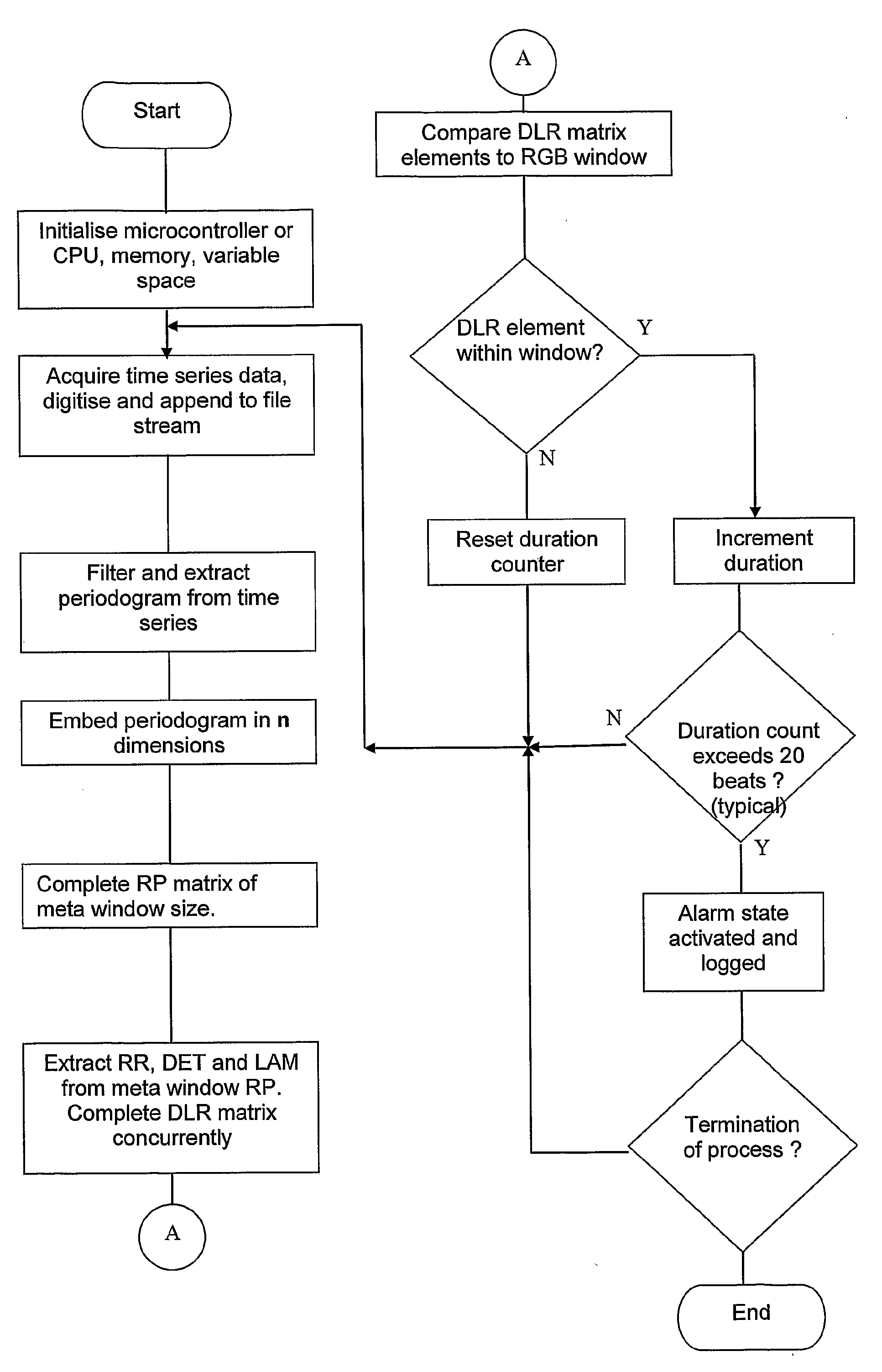
[0063]In a first embodiment, a fixed system in which biosignals representative of heart rate are digitised, stored and analysed using the DLR method is implemented as per the flowchart of FIG. 5. A bioamplifier provides signal conditioning to biopotentials obtained from surface electrodes applied to the subject. An analog to digital conversion provides a raw signal from which a beat-to-beat interval can be found using known techniques. This period versus time, or tachogram, is then a suitable data stream for application to the DLR method. Such a fixed system has application, for example, to bedside monitoring for the purpose of real time alarm activation. Analysis of data after it has been collected is of use for identifying at risk patterns. Therapeutic actions may then be taken on the basis of this analysis.

second embodiment

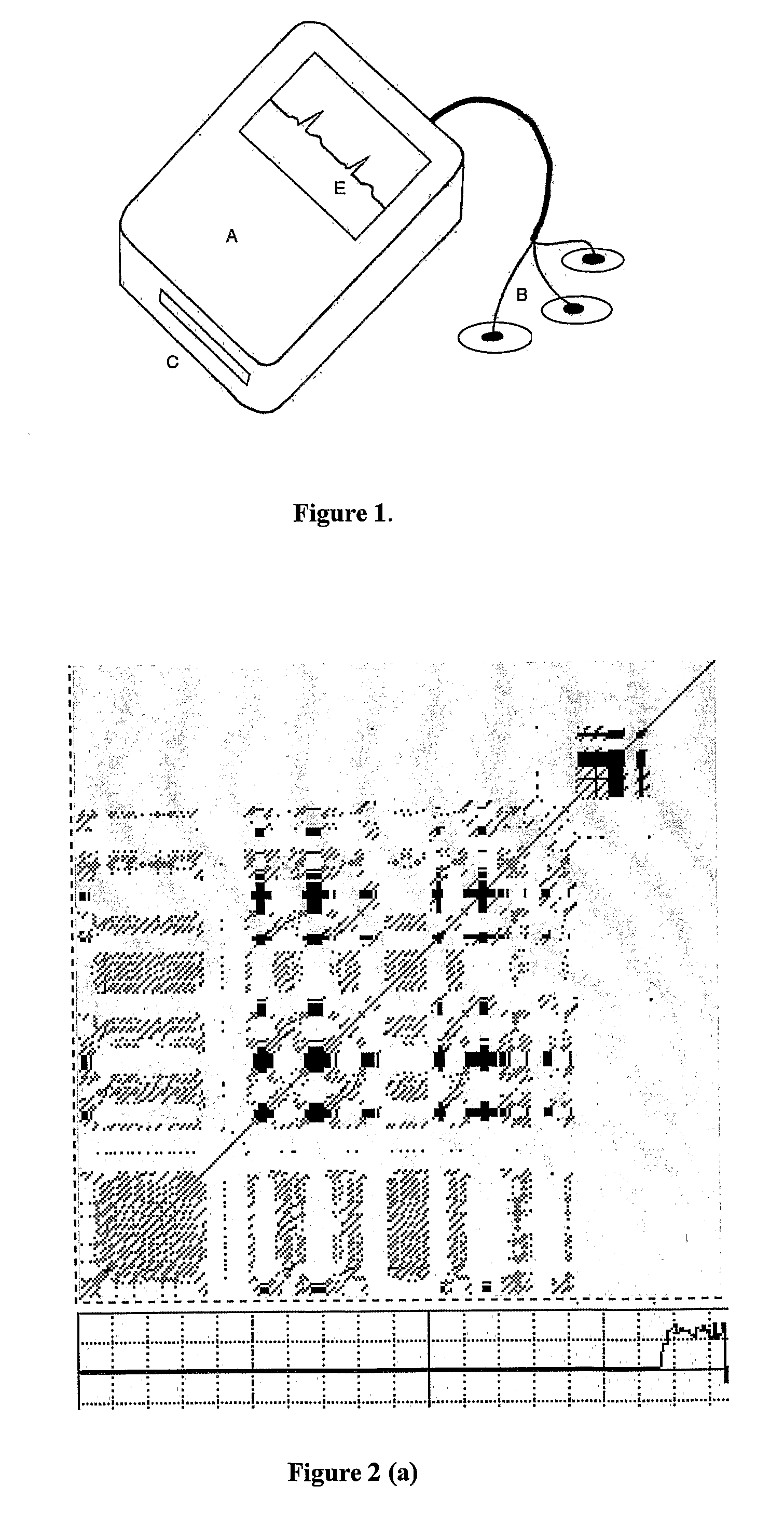
[0064]A second embodiment is optimised for ambulatory or portable use. The purpose of such a device is primarily for alarming the subject and / or clinician of the incipient risk of potentially dangerous rhythms. A storage function allows post hoc analysis and archived alarm states to be retrieved for review and the exercising of therapeutic options.

[0065]The ambulatory recording device is formed in the shape shown in FIG. 1 with a display window and a plurality of user operated switches. A cable consisting of a number of conductive leads exits the enclosure and is applied to the subject. A removable memory card is accessible but hidden for normal use.

[0066]The display can show real time signal as well as confirm operating status to the user.

[0067]The device can be operated by firmware to carry out the two general roles of managing an operating system and recording, as well as analysis in which an implementation of recurrence analysis is operating.

[0068]A signal acquired from a period...


PUM


Abstract

Biological data, such as human heart rate data, is acquired and processed in a non-linear manner to facilitate an assessment of the physiological state of the subject, and / or to assist in predicting incipient disorders or instability. Determinism, laminarity and recurrence measures are derived for a rolling sample of a time series of said data. The recurrence measure can be the Euclidean threshold (εthresh) at a given recurrence rate. A representation, such a colour coded matrix or multi-dimensional vector, is formed from a combination of the derived determinism, laminarity and recurrence measures. The representation can then be analysed to detect indicators of physiological instability, such as arrhythmia, or to discriminate between arrhythmias. The analysis may be performed visually, or in an automated manner in real time, such as in an ambulatory or implanted device, or post hoc by a bedside monitor.

Description

[0001]This invention relates to a medical monitoring system, and in particular, a system for predicting physiological arrhythmias. In a preferred embodiment, the invention comprises an ambulatory health monitoring and alarm system which utilises non-linear analysis of acquired electrocardiographic data in real time, and the generation of an alarm state or risk quantification for impending arrhythmia.[0002]However, the scope of the invention is not necessarily limited thereto. Physiological time series data other than electrocardiographic signals can be subject to such analysis with the aim of predicting the likelihood of relevant system instability. Moreover, the invention may be embodied in ambulatory, implanted or fixed-bedside devices, as well as in post hoc analysis.BACKGROUND ART[0003][Mere reference to background art herein should not be construed as an admission that such art constitutes common general knowledge or prior art in relation to this application.][0004]Electrocardi...

Claims


Application Information

Patent Timeline
Patent Type & Authority Applications(United States)
IPC IPC(8): A61B5/0402A61B5/363
CPCA61B5/044G06K9/00496A61B5/0464A61B5/0452A61B5/339A61B5/363A61B5/349G06F2218/00
Inventor CROZIER, STUARTWILSON, STEPHENDING, HANG
Owner QUEENSLAND THE UNIV OF
Why Eureka
Try Eureka