
Gastro-tube using a shape-retentive alloy and method of use thereof

a technology of shape-retentive alloy and tube, applied in the field of medicine, can solve the problems of tube used in such methods, and achieve the effect of easy pull-out and easy pull-out operation

Inactive Publication Date: 2008-05-29
TAKUMA NORIKATA
View PDF5 Cites 0 Cited by
  • Summary
  • Abstract
  • Description
  • Claims
  • Application Information

AI Technical Summary

Benefits of technology

"The present invention relates to a gastrostomy tube for patients who cannot ingest sufficient food orally. The technical effects of the invention include the use of a shape memory alloy at the leading end of the tube to prevent slipping out during use and ease of removal during replacement, as well as the use of opening enlarging forceps for easy re-insersion of the tube. The invention also provides a method for using the gastrostomy tube with the forceps for regular replacement of the tube. The tools for reinserting the gastrostomy tube are easy to use, and the pull-out operation is simple."

Problems solved by technology

As described above, a PEG method is effective for feeding for patients who are unable to ingest sufficient food orally; however, a tube used in such method has several problems.

Method used


Image

  • Gastro-tube using a shape-retentive alloy and method of use thereof
  • Gastro-tube using a shape-retentive alloy and method of use thereof
  • Gastro-tube using a shape-retentive alloy and method of use thereof

Examples


embodiment 1

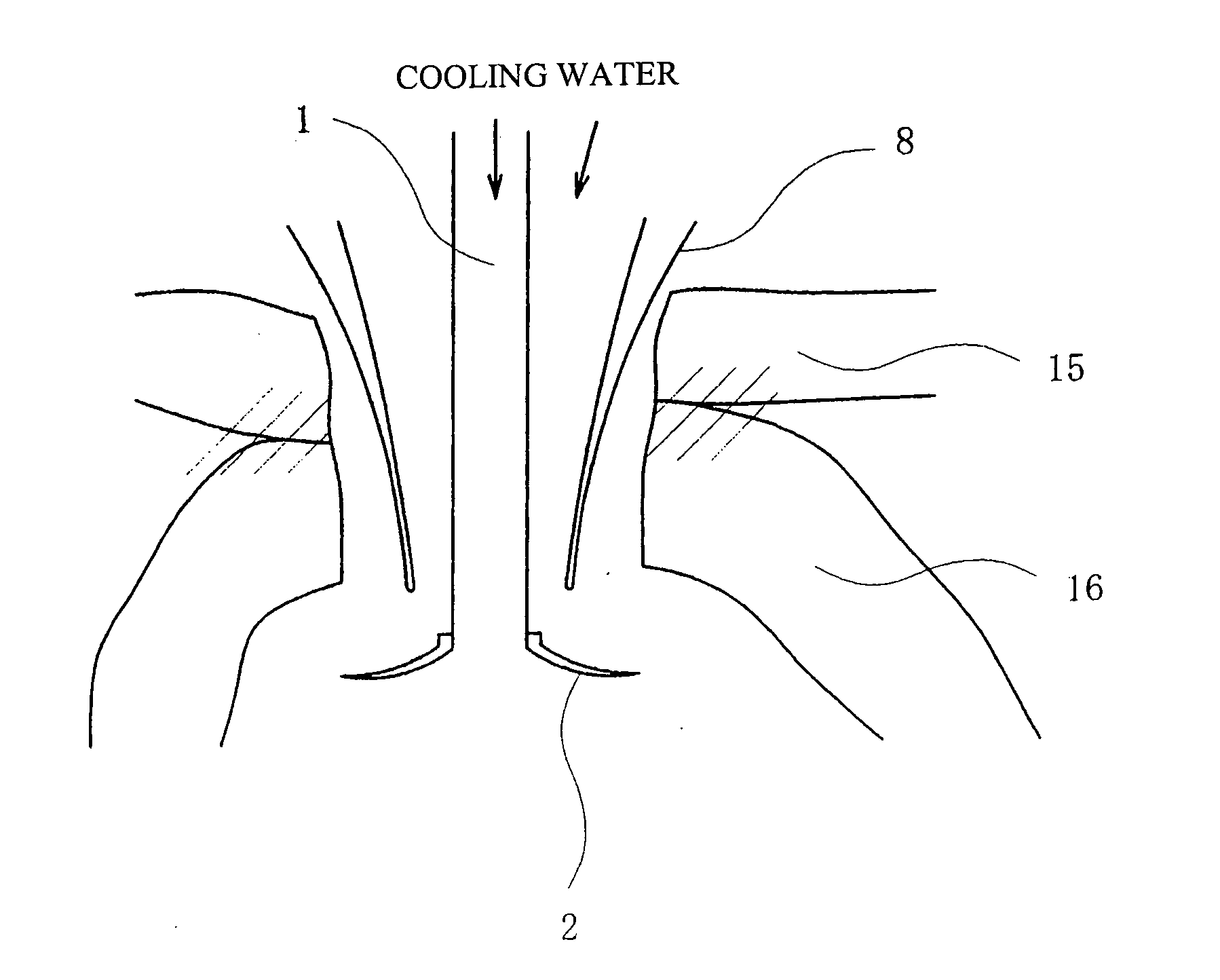
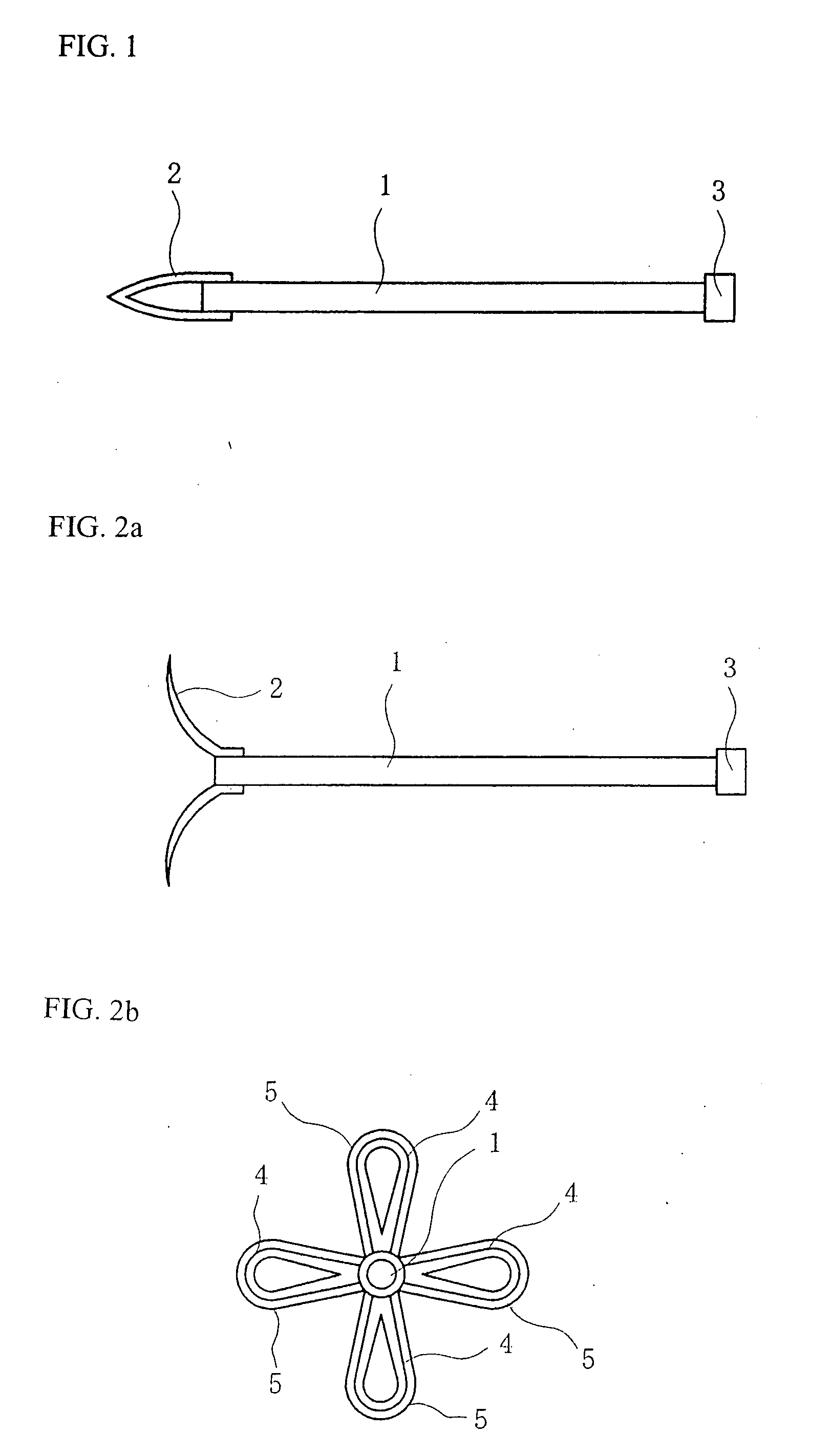
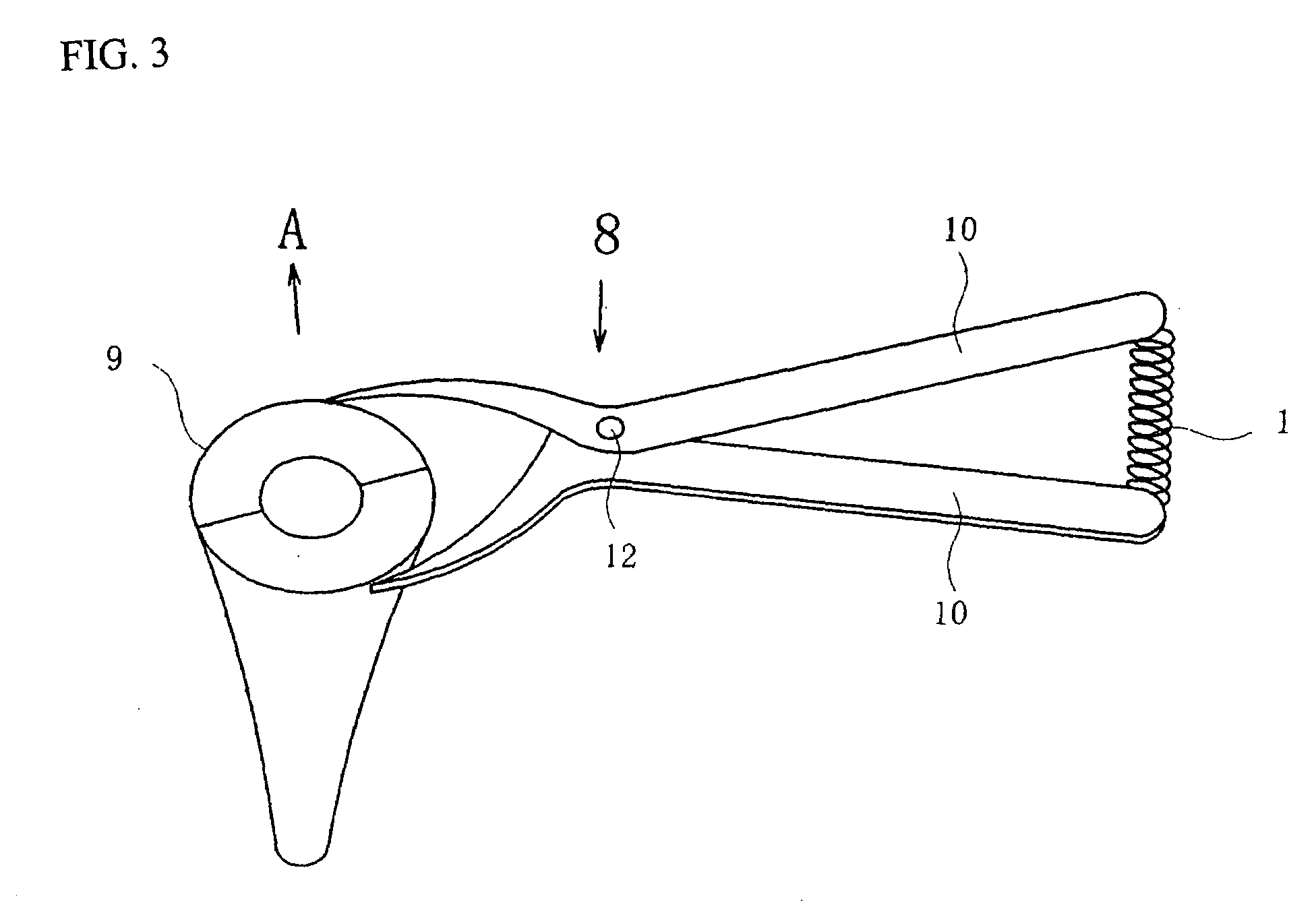
[0054]FIG. 1 is an oblique view showing a gastrostomy tube 1 of the present invention. The gastrostomy tube 1 is formed in a cylindrical body having an outer diameter of about 7 mm to 9 mm and a smooth circular cross-sectional outline, and when combined with a lower end of a funnel-shaped part 9 of opening enlarging forceps 8, the tube is in close contact therewith and can slide smoothly in the vertical direction.

[0055]The gastrostomy tube 1 has a leading end on which a Cu—Zn shape memory alloy wire 4 having a diameter of 2 mm is folded in a roughly oval shape, and around the wire, four pull-out prevention pieces 2 coated with a transparent resin material 5 are attached integrally therewith. Further, the gastrostomy tube 1 has a rear end on which a joint 3 is provided so that a syringe (not shown in the drawings) can be connected thereto.

[0056]FIGS. 2(a) to 2(b) are diagrams for explaining a state where the four pull-out prevention pieces 2 are warmed by body temperature within a st...

embodiment 2

[0078]Another gastrostomy tube of the present invention is configured such that two shape memory alloys are used in combination for the pull-out prevention pieces; one assumes a petal shape at a temperature lower than normal body temperature (for example, 25° C.), and the other assumes a closed-petal shape at a temperature higher than normal body temperature (for example, 43° C.).

[0079]To insert such a gastrostomy tube into an opening, as in embodiment 1, the pull-out prevention pieces at the tube leading end are narrowed in cold water to enable passage through the opening secured by the opening enlarging forceps. If in this state the body temperature is transmitted to the pull-out prevention pieces so that the temperature thereof reaches 25° C., the pull-out prevention pieces open due to the operations of the shape memory alloy for a lower temperature, thereby preventing pull-out of the tube.

[0080]At time of regular replacement and the like of gastrostomy tubes, as in embodiment 1,...


PUM


Abstract

A gastrostomy tube of the present invention which includes a tube body formed as a cylindrical body and a leading end to which shape memory alloy pull-out prevention pieces are attached is used in combination with opening enlarging including forceps including a funnel-shaped part having a leading end divided into two, two gripping rods respectively fixed to the sides of the funnel-shaped part, and a spring part fixed to the rear end of the supporting rods.

Description

BACKGROUND OF THE INVENTION[0001]The present invention relates to the provision, in the field of medicine, of fluids and nourishment to patients unable to ingest orally; more particularly, it relates to the improvement of a tube for use in gastrostomy, a type of enteral feeding.[0002]Conventionally, patients who are suffering from severe brain damage and / or dementia, and are unable to normally ingest food orally require enteral feeding. Methods for inserting a feeding tube can be broadly classified into the following categories:(1) passing a tube through an anatomically existing space; and(2) creating a new route for tube insertion (e.g., gastrostomy).[0003]Providing fluids and nutrition using percutaneous endoscopic gastrostomy (PEG) is essential for the survival of patients, and such a method depends upon a medical tool called a gastrostomy tube. When we consider the functions that are required of a gastrostomy tube, we find that they fall into three categories:a. ease of insertio...

Claims


Application Information

Patent Timeline
Patent Type & Authority Applications(United States)
IPC IPC(8): A61M25/04
CPCA61B17/3415A61J15/0015A61J15/0023A61J15/0026A61J15/0038
Inventor TAKUMA, NORIKATA
Owner TAKUMA NORIKATA
Learn More