Shunt Valve Locking Mechanism

a locking mechanism and valve technology, applied in mechanical control devices, process and machine control, instruments, etc., can solve problems such as affecting the function of fluid flow control devices, affecting the speed of shunt valves, and increasing brain pressure, so as to prevent any unintentional adjustment, overcome disadvantages, and achieve the effect of preventing any unintentional adjustmen

Inactive Publication Date: 2008-06-05
INTEGRA LIFESCI SWITZERLAND SARL
View PDF7 Cites 13 Cited by
  • Summary
  • Abstract
  • Description
  • Claims
  • Application Information

AI Technical Summary

Benefits of technology

[0010]The present invention overcomes the disadvantages that are inherent in prior art fluid management systems by providing a locking assembly that simply and effectively prevents any unintentional adjustment of an adjustable valve mechanism in a fluid flow control device, without compromising the function of the fluid flow control device. The locking assembly of the present invention generally includes at least one gripping arm for frictionally engaging at least a portion of the adjustable valve mechanism, and an actuating mechanism for controlling the deployment and release of the at least one gripping arm. The loc

Problems solved by technology

Blockage of the flow of CSF consequently creates an imbalance between the rate at which CSF is produced by the ventricular system and the rate at which CSF is absorbed into the bloodstream.
This imbalance increases pressure on the brain and causes the ventricles to enlarge.
Left untreated, hydrocephalus can result in serious medical conditions, including subdural hematoma, compression of the brain tissue, and impaired blood flow.
However, these magnetized rotors can be unintentionally adjusted in the presence of a strong external magnetic field,

Method used


Image

  • Shunt Valve Locking Mechanism
  • Shunt Valve Locking Mechanism
  • Shunt Valve Locking Mechanism

Examples


Embodiment Construction

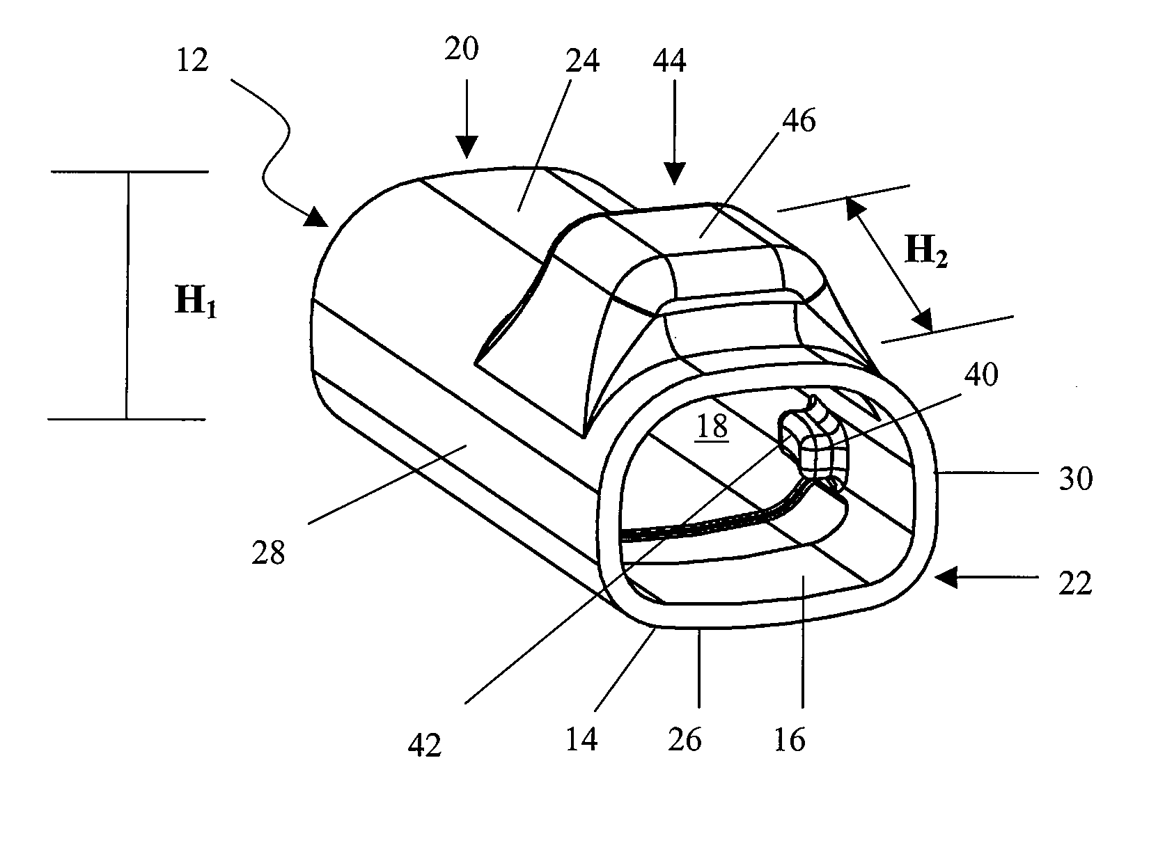
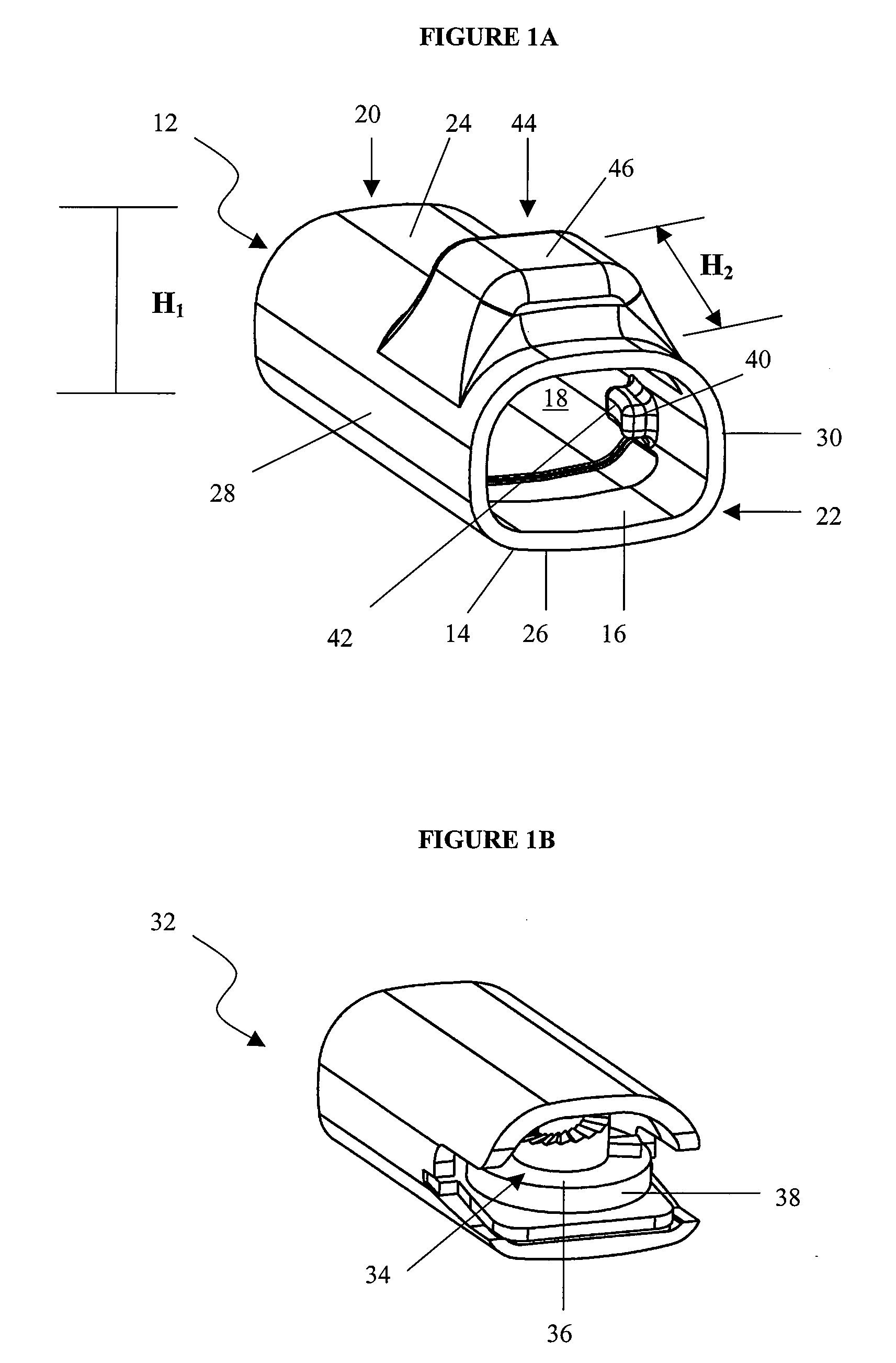
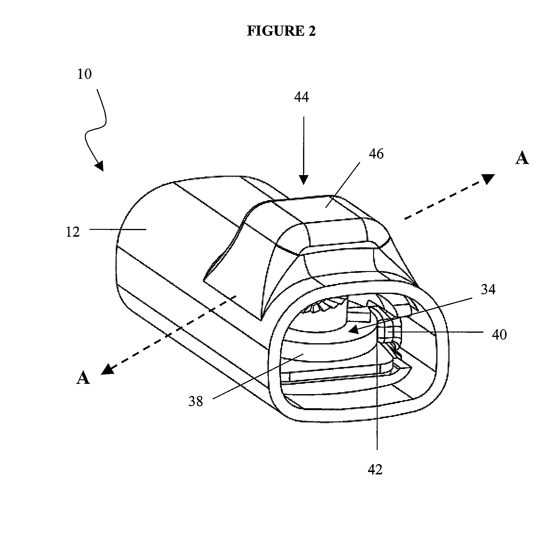
[0020]The locking assembly of the present invention stably maintains an adjustable valve mechanism of an adjustable fluid flow control device in a desired position, thereby preventing any unintentional adjustments of the fluid flow control device. Generally, the locking assembly of the present invention includes at least one gripping arm that is operatively joined to an actuating mechanism and can control the deployment and release of the at least one gripping arm. The locking assembly prevents unintentional adjustments that can adversely affect the pressure settings of the fluid flow controlling medical device. In particular, the locking assembly prevents unintentional adjustment in the presence of a strong external magnetic field, such as for example, the strong unidirectional magnetic field encountered in an MRI procedure. The locking assembly can be easily disengaged, through the application or removal of an external mechanical force, thereby allowing a clinician to adjust the p...


PUM


Abstract

A locking assembly is provided to simply and effectively prevent any unintentional adjustment of the adjustable valve mechanism in a fluid flow control device, without compromising the function of the device. The locking assembly generally includes at least one gripping arm for frictionally engaging at least a portion of the adjustable valve mechanism, and an actuating mechanism for controlling the deployment and release of the gripping arm. The locking assembly prevents unintentional adjustments that can adversely affect the pressure settings of the fluid flow control device. In particular, the locking assembly prevents unintentional adjustment, such as may be caused by the presence of a strong external magnetic field. The locking assembly can be easily disengaged, such as through the application or removal of an external mechanical force, to allow a clinician to adjust the pressure settings of the fluid flow control device as necessary.

Description

CROSS-REFERENCE TO RELATED APPLICATIONS[0001]The present application is a divisional of U.S. patent application Ser. No. 10 / 192,394 filed on Jul. 10, 2002 and entitled “Shunt Valve Locking Mechanism” which is hereby incorporated by reference in its entirety.FIELD OF THE INVENTION[0002]The present invention relates generally to medical devices for directing bodily fluids from one region of a patient to another region. More specifically, this invention relates to shunt systems having an adjustable shunt valve to control the flow of fluid through the system and, even more specifically, a locking mechanism to control the adjustment of the shunt valve.BACKGROUND OF THE INVENTION[0003]Hydrocephalus is a neurological condition caused by the abnormal accumulation of cerebrospinal fluid (CSF) within the ventricles, or cavities, of the brain. Hydrocephalus, which can affect infants, children and adults, arises when the normal drainage of CSF in the brain is blocked in some way. Such blockage ...

Claims


Application Information

Patent Timeline
IPC IPC(8): F16K35/00A61M27/00A61M1/00A61M39/00F16K35/02F16K35/04
CPCA61M27/006F16K35/04F16K35/025Y10T137/7256Y10T137/7069Y10T137/7225Y10T70/5615
Inventor MCCUSKER, DANIELDEXTRADEUR, ALAN J.GUPTA, RAINUKASOUTHWORTH, CARLETON BRYAN
Owner INTEGRA LIFESCI SWITZERLAND SARL
Why Eureka
Try Eureka