Stent crimping assembly and method

a crimping assembly and stent technology, applied in the field of intraluminal devices, can solve the problems of slipping of stents that are not properly crimped, secured or retained to the delivery catheter, and slipping of stents, so as to avoid uneven radial crimping force on the stent, and increasing the risk of thrombosis

Inactive Publication Date: 2008-06-05
ABBOTT LAB INC
View PDF51 Cites 45 Cited by
  • Summary
  • Abstract
  • Description
  • Claims
  • Application Information

AI Technical Summary

Benefits of technology

[0015]In another aspect of the present invention, a stent crimping assembly is provided for crimping a stent from a first diameter to a reduced second diameter. The crimping assembly includes a set of two or more blade devices each having a first end, a second end, and a respective edge wall in opposed relationship to one another. Each respective edge wall tapers inwardly from the respective one ends to the respective second ends, relative to a common longitudinal axis of an elongated crimp aperture collectively defined by the opposed edge walls in a respective crimp position. Each respective one ends collectively defining a receiving port into the crim

Problems solved by technology

Stents that are not properly crimped, secured or retained to the delivery catheter may slip and will either be lost, be deployed in the wrong location or only be partially deployed.
In the past, crimping has been performed by hand, often resulting in an undesirable application of uneven radial crimping forces to the stent.
Sten

Method used


Image

  • Stent crimping assembly and method
  • Stent crimping assembly and method
  • Stent crimping assembly and method

Examples


Embodiment Construction

[0036]While the present invention will be described with reference to a few specific embodiments, the description is illustrative of the invention and is not to be construed as limiting the invention. Various modifications to the present invention can be made to the preferred embodiments by those skilled in the art without departing from the true spirit and scope of the invention as defined by the appended claims. It will be noted here that for a better understanding, like components are designated by like reference numerals throughout the various figures.

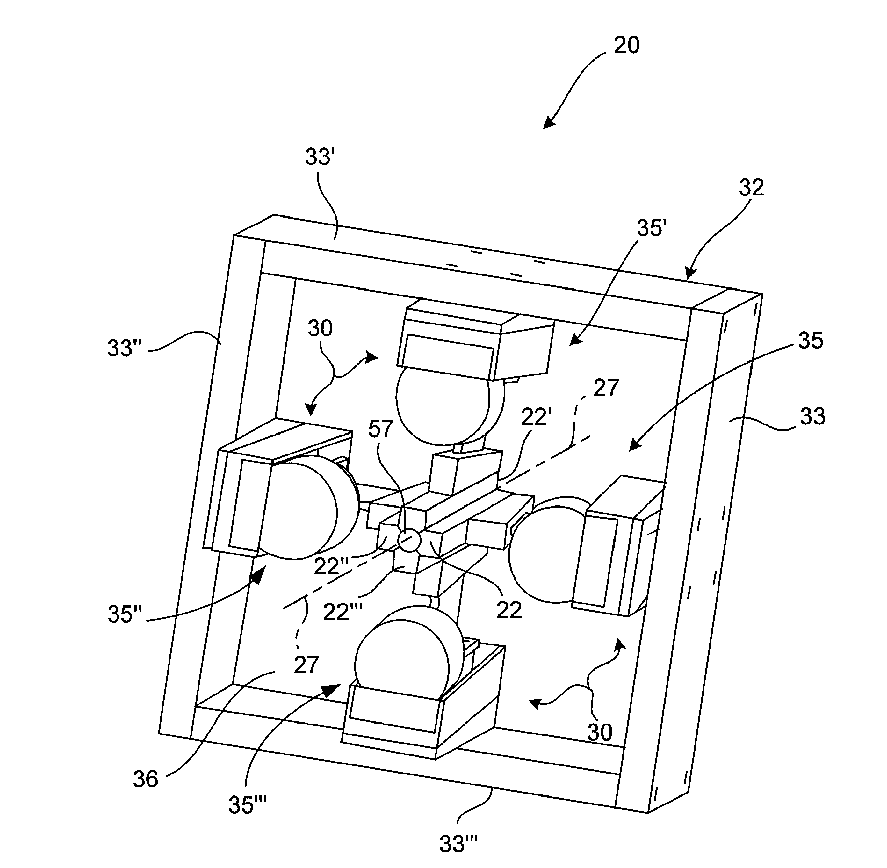
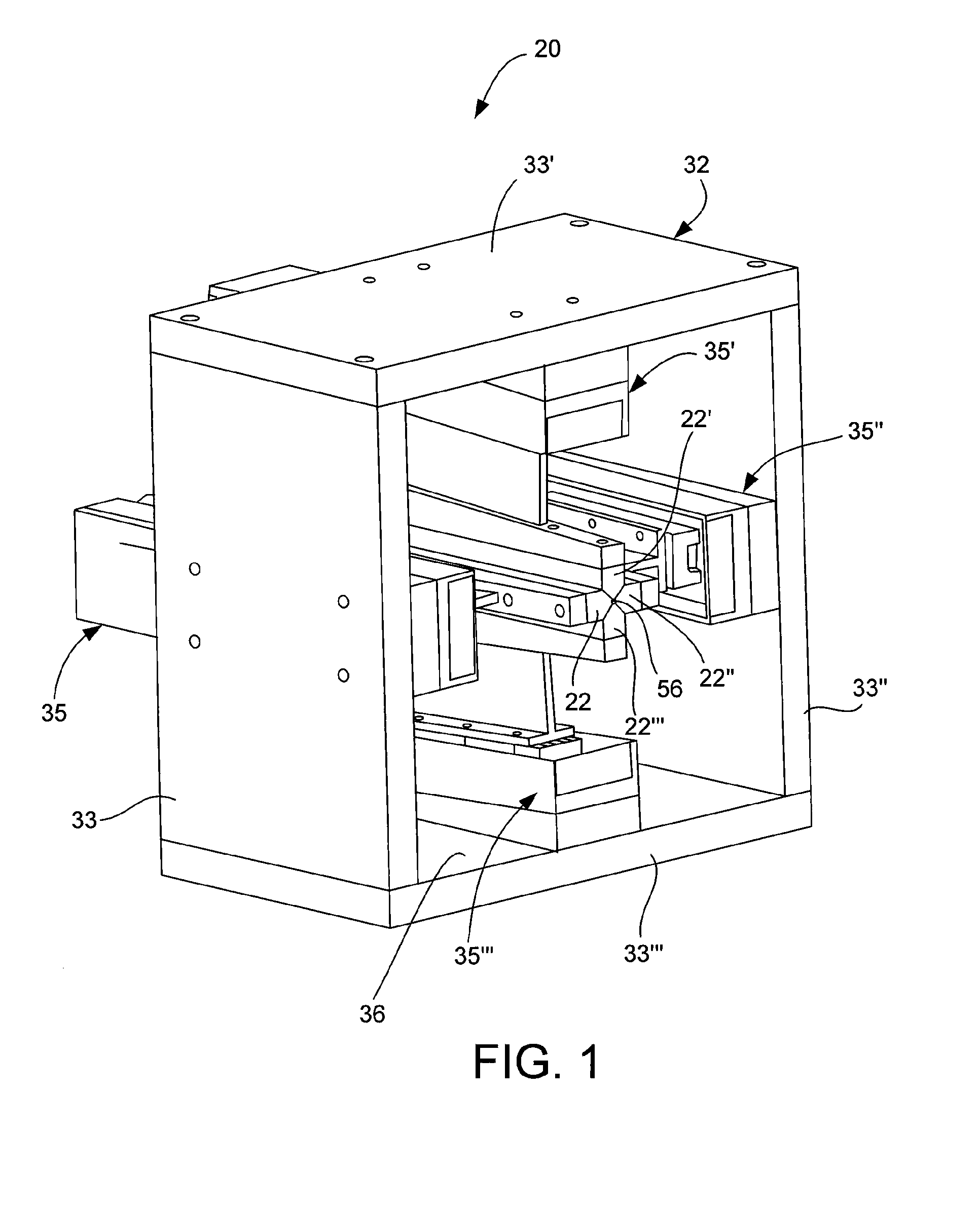
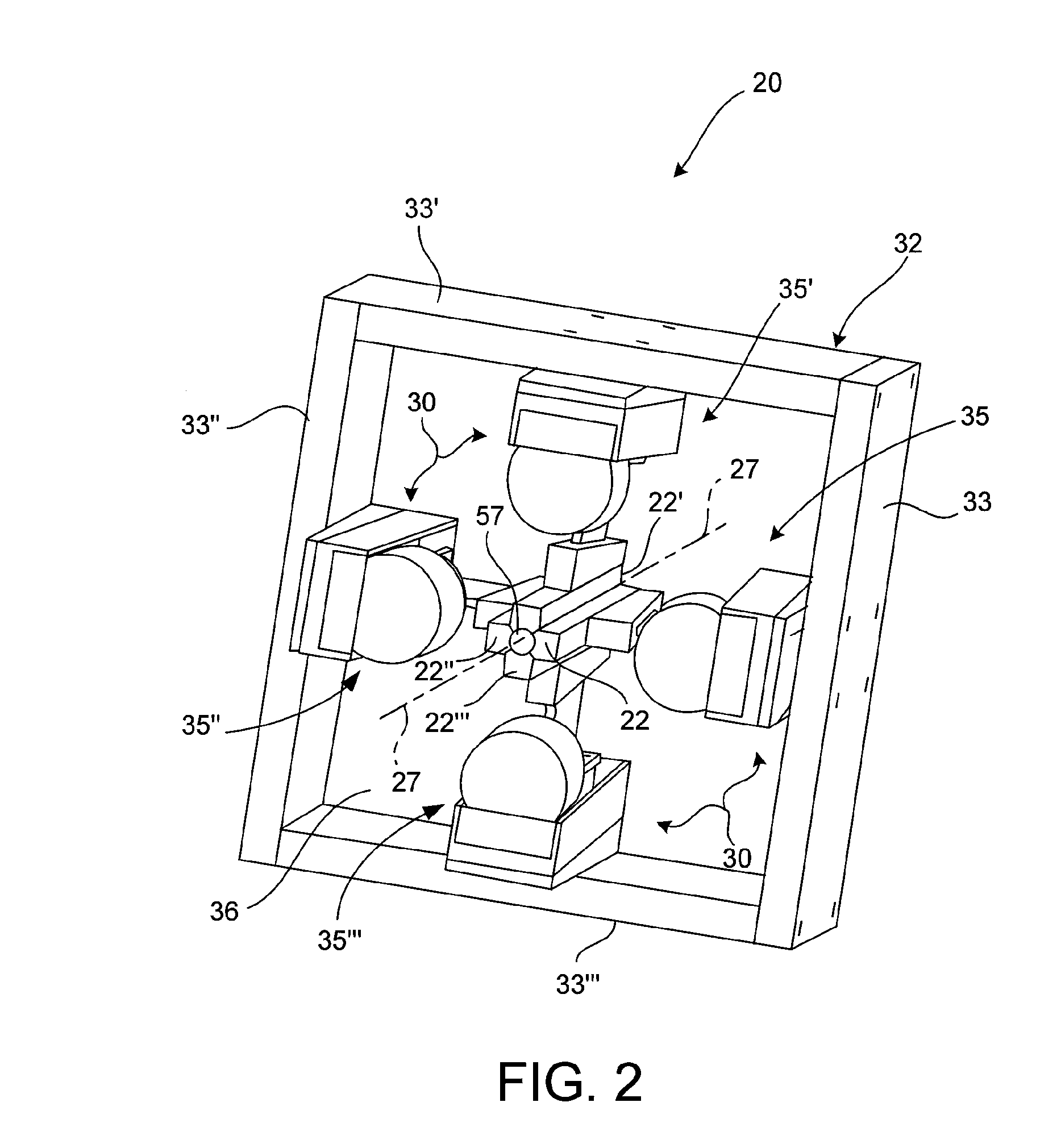
[0037]Referring now to FIGS. 1-4 and 7-8G, a stent crimping assembly, generally designated 20, is provided for crimping a stent 21 from a first diameter to a reduced second diameter. The crimping assembly 20 includes a set of two or more blade devices 22, 22′, 22″, . . . 22n (were n=total number of the blade devices) each having a respective proximal portion 23, 23′, 23″, . . . 23n, a respective distal portion 25, 25′, 25″, . . . 2...


PUM

PropertyMeasurementUnit
Angleaaaaaaaaaa
Diameteraaaaaaaaaa
Dimensionaaaaaaaaaa

Abstract

A stent crimping assembly is provided for crimping a stent from a first diameter to a reduced second diameter. The assembly includes a set of two or more blade devices each having a proximal portion, a downstream distal portion, and a respective edge wall extending from the proximal portion to the distal portion. Each respective edge wall is oriented relative to one another, in a respective crimp position, to collectively define an elongated conical-shaped crimp aperture. The conical-shaped crimp aperture at the respective proximal portion of each blade is formed for receipt of at least a portion of the stent in the first diameter. The crimping assembly further includes a drive assembly associated with each blade device and configured to independently displace each blade edge wall in a manner substantially along a respective predetermined first path from the respective crimp position to a respective retracted position, oriented a predetermined incremental distance from the crimp position in a respective proximal direction.

Description

RELATED APPLICATION DATA[0001]The present application claims priority under 35 U.S.C. §119 to U.S. Provisional Application Ser. No. 60 / 872,134, naming Arkady Kokish et al as inventors, filed Nov. 30, 2006, and entitled STENT CRIMPING ASSEMBLY AND METHOD, which is incorporated herein by reference in its entirety and for all purposes.FIELD OF THE INVENTION[0002]The present invention relates generally to intraluminal devices, and more particularly relates to apparatus and methods for diametrically reducing the size of these devices, such as a stent, stent-graft, graft or vena cava filter, for percutaneous transluminal delivery thereof.BACKGROUND OF THE INVENTION[0003]A number of vascular diagnostic and interventional medical procedures are now performed translumenally. For example, a catheter is introduced into the vascular system at a convenient access location and guided through the vascular system to a target location using established techniques. Such procedures require vascular ac...

Claims


Application Information

Patent Timeline
IPC IPC(8): B21D41/04A61F2/06
CPCA61F2/95A61F2002/9522A61F2/958A61F2/9522A61F2/9525
Inventor KOKISH, ARKADYSHUMER, DANIEL H.
Owner ABBOTT LAB INC
Why Eureka
Try Eureka