Plumbing valve with stick control handle

a technology of control handle and grip, which is applied in the direction of valve operating means/release devices, mechanical equipment, transportation and packaging, etc., can solve the problems of inability to meet the needs of use, inability to adjust the grip, etc., to achieve the effect of reducing the wear and tear of the internal moving parts, reducing the risk of damage, and facilitating assembly and maintenan

Active Publication Date: 2008-06-05
KOHLER CO
View PDF11 Cites 11 Cited by
  • Summary
  • Abstract
  • Description
  • Claims
  • Application Information

AI Technical Summary

Benefits of technology

[0016]One important advantage of the present invention is that the spring provides a resilient loading to the joystick, or from the joystick. Further, when a sliding disk is used to cover the connection between the handle, the lever and the control valve, the disk can be provided with a self-lubricating bearing. In any event, it helps seal out water, debris and cleaning solutions.
[0017]The resiliency of the joystick connection also minimizes wear on the internal moving parts, while providing an aesthetically pleasing feel. Importantly, the location for a spring outside the main housing facilitates assembly and maintenance.
[0018]Another advantage of the resilient connection is that it reduces the likelihood of cracking the cabinet or other associated supporting box. For example, the associated mirror of the cabinet may be somewhat fragile. The extra give provided by the spring is an important safeguard in reducing excess pressure.
[0019]Yet another advantage of the present invention is that when these faucets are used with aesthetically pleasing cabinet and other box housings, with appropriate positioning of an outlet nozzle a user can only see the joystick control and an exiting water stream. Particularly where the nozzle creates a laminar flow, this creates a highly desirable aesthetic appearance.
[0020]These and still other advantages of the present invention will be apparent from the detailed description which follows and the accompanying drawings. Hence, the following claims should be looked to in judging the full scope of the invention.

Problems solved by technology

However, a problem with many of these designs is that pressure on the control handle during actuation can eventually cause the handle connection to loosen, which can allow the handle to inadvertently actuate or wobble.
Further, over time some of these devices require a relatively large force to cause movement of the valve components, which can expedite degradation of valve internal components.
Even where this is not the case, many of these designs are undesirably susceptible to wear and tear.
Still other of these designs do not effectively preclude environmental water, soap and dirt from entering the valve.
Again, this can adversely affect performance.
However, existing prior art designs suffer from one or more deficiencies (e.g. those noted above).

Method used


Image

  • Plumbing valve with stick control handle
  • Plumbing valve with stick control handle
  • Plumbing valve with stick control handle

Examples


Embodiment Construction

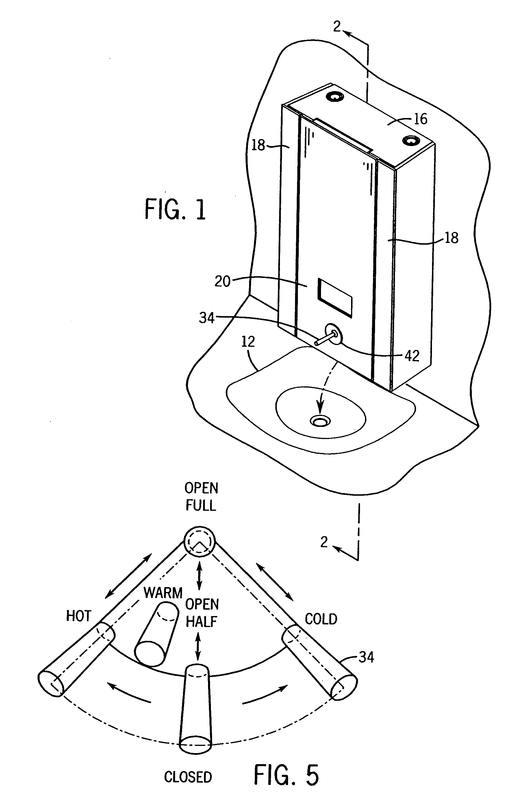
[0031]Referring first to FIGS. 1-6, there is shown a sink 12 and a cabinet 16 having a faucet 14 associated therewith. The internal central portion of the cabinet 16 can contain plumbing connections and most of the parts of the faucet. The sides 18 of the cabinet can be in the form of swing-out hide-away shelves.

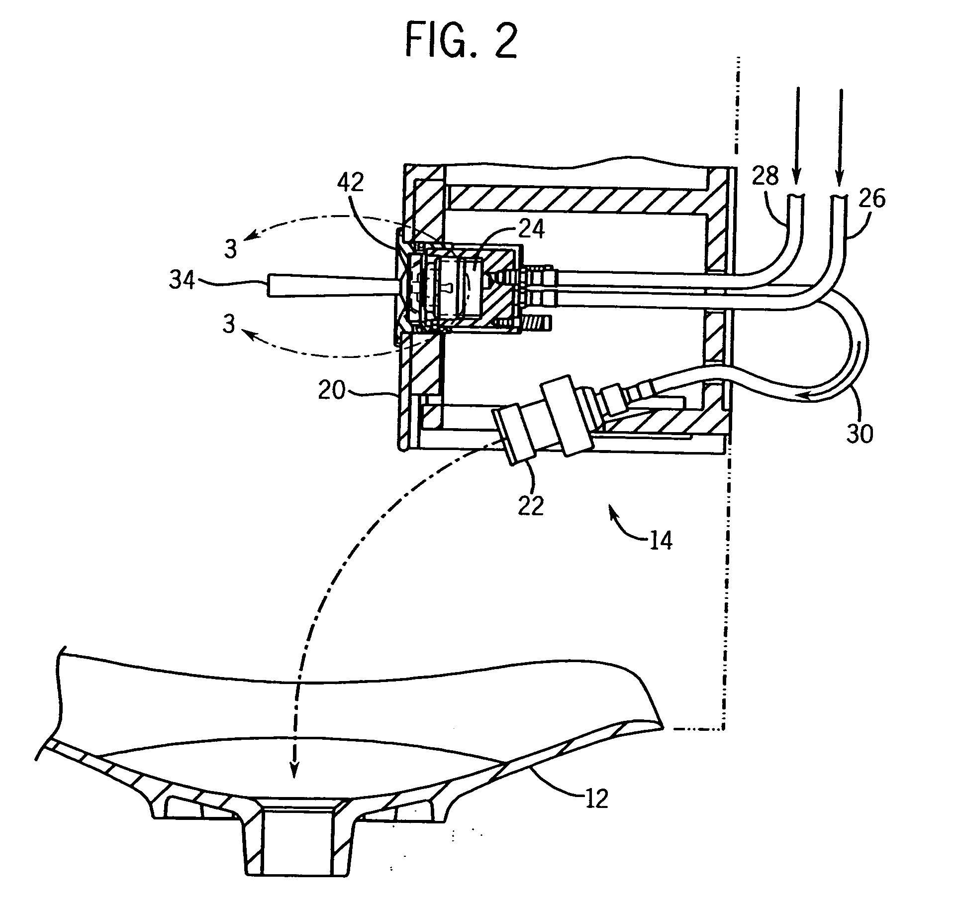
[0032]Faucet 14 includes a front 20, which can be part of cabinet 16 (e.g. a mirrored front surface of cabinet 16) or can otherwise be part of a faucet housing. A outlet spout 22 is connected to the faucet 14, and a mixing valve cartridge 24 is in fluid communication with spout 22.

[0033]The precise mixing valve used is not critical provided that it can be controlled by joystick movement. For example, the mixing valve of U.S. Pat. No. 6,209,581, incorporated herein by reference, could be used to control water flow from hot and cold inlets to the outlet spout 22. Alternatively, one could select other commercial ceramic mixing valves such as the Kerox Model GN-40A, which is adv...


PUM


Abstract

Faucets are provided with joystick type control handles. The joysticks are provided with springs outside the main valve housing either between the joystick handle and lever stick, or between the joystick handle and an associated ball. In the latter case the ball retains a sliding disk.

Description

CROSS-REFERENCE TO RELATED APPLICATION[0001]Not applicable.STATEMENT OF FEDERALLY SPONSORED RESEARCH OR DEVELOPMENT[0002]Not applicable.BACKGROUND OF THE INVENTION[0003]The present invention relates to plumbing valves such as faucets. More particularly it relates to such valves which are controlled by a joystick type handle control.[0004]A wide variety of plumbing control valves are known which use a single lever handle to control volume and mixing. Typically the handle extends through the top or front of a valve housing with its inner end linked to sliding and / or rotating plates or other control structures. The outer end of the handle is designed to be gripped by the consumer. See e.g. U.S. Pat. Nos. 1,798,530, 2,850,042, 3,512,547, 3,548,878, 3,693,660, 4,357,957, 4,916,966, 5,095,934, 6,209,581 and 6,286,808.[0005]However, a problem with many of these designs is that pressure on the control handle during actuation can eventually cause the handle connection to loosen, which can al...

Claims


Application Information

Patent Timeline
Patent Type & Authority Applications(United States)
IPC IPC(8): F16K11/00
CPCE03C1/04F16K31/605E03C1/0412Y10T137/86815Y10T137/86823Y10T137/9464
Inventor FLEISCHMANN, GARY A.
Owner KOHLER CO
Why Eureka
Try Eureka