Air Bacteria Removal Device

Inactive Publication Date: 2008-06-05
SANYO ELECTRIC CO LTD
View PDF3 Cites 4 Cited by
  • Summary
  • Abstract
  • Description
  • Claims
  • Application Information

AI Technical Summary

Benefits of technology

[0008]The present invention has been developed to solve such problems of the conventional technology, and an object thereof is to provide an air bacteria removal device in which leakage of electrolytic water to the outside is eliminated as much as possible and in which maintenance can easily be performed.

Problems solved by technology

However, there is a restriction on a space in which the electrolytic water mist can be scattered.
Therefore, the above-mentioned bacteria removal device is effective in a small space in which the electrolytic water mist can be scattered, but has a problem that the effect cannot easily be exhibited in a large space such as a public facility or a vehicle.
Furthermore, the above-mentioned conventional bacteria removal device has disadvantages that a large amount of water for producing the mist is used in order to scatter the mist of the electrolytic water in the space and that the space is humidified by the mist to fog a window.
Furthermore, the device needs to have a structure capable of collecting at least the electrolytic water excessively supplied to the air-liquid contact member, and hence problems have occurred that the structure is complicated, the device is enlarged and costs soar.
In addition, since dust in the air and a scale in the electrolytic water stick to the air-liquid contact member, daily maintenance such as cleaning is required, but such a structure also has a problem that it is difficult to remove the air-liquid contact member from the air bacteria removal device.
Furthermore, in such a structure, sealability cannot easily be secured, and the electrolytic water might leak to the outside in a case where the device tilts.
Therefore, many problems to solve are left in practically using the conventional bacteria removal device as the air bacteria removal device in a vehicle such as a car or a train.

Method used


Image

  • Air Bacteria Removal Device
  • Air Bacteria Removal Device
  • Air Bacteria Removal Device

Examples


Embodiment Construction

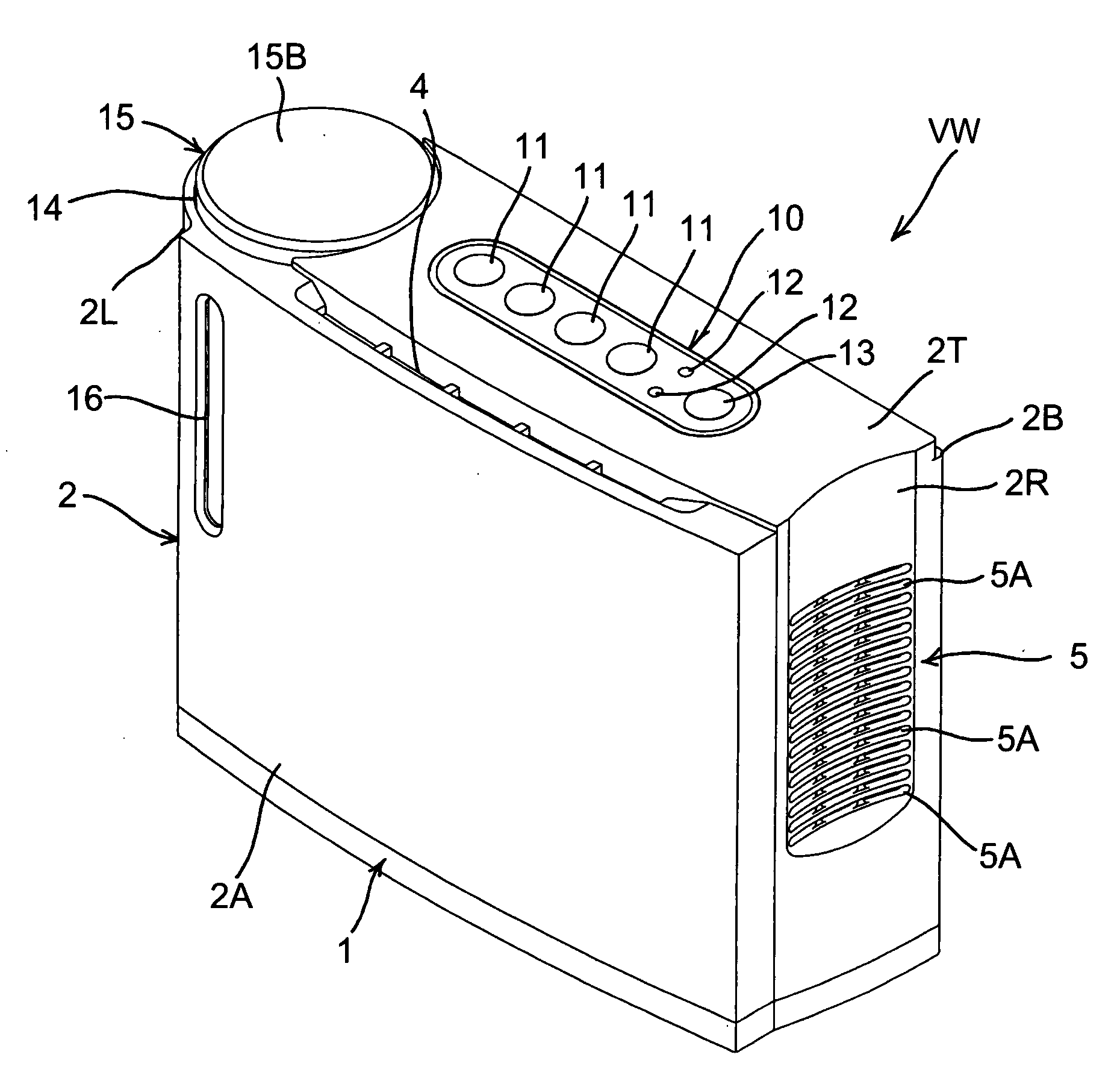
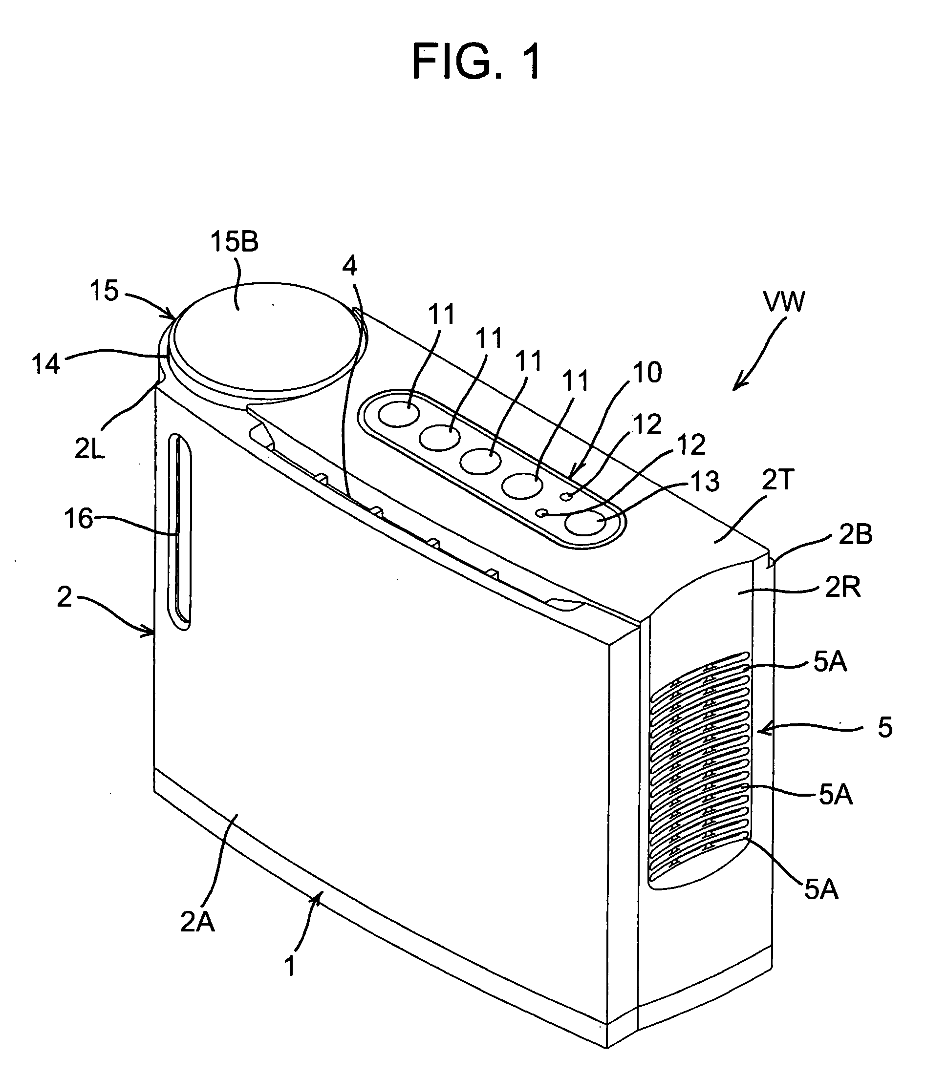
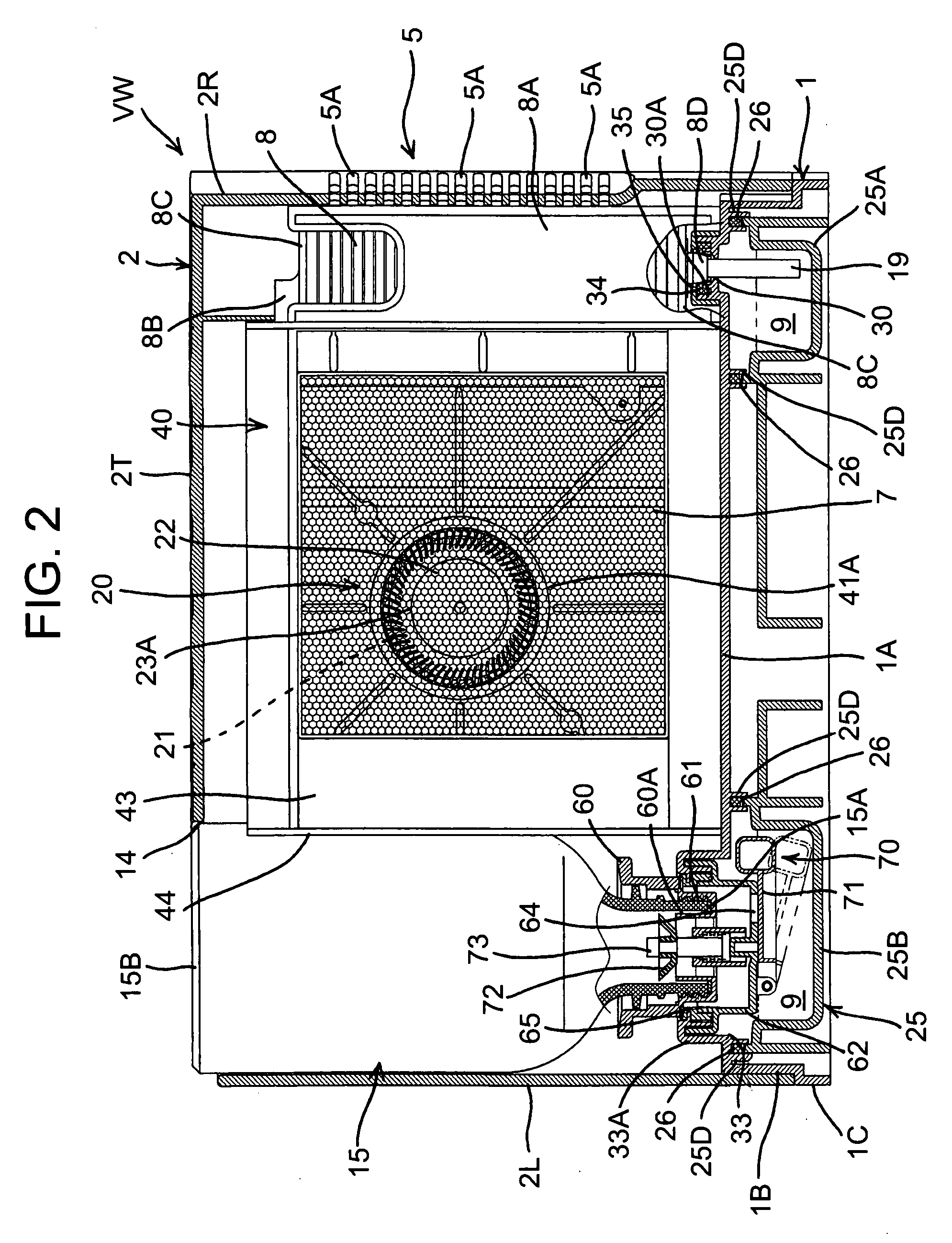
[0043]The present invention relates to an air bacteria removal device in which an air-liquid contact member brings electrolytic water into contact with passed air to remove microorganisms floating in air and the like, and the device has been developed in order to easily realize maintenance of the air-liquid contact member while eliminating a disadvantage that the electrolytic water leaks to the outside as much as possible. An object to provide an air bacteria removal device in which the water leakage is eliminated as much as possible and in which maintenance can easily be performed is achieved by a device including a main body having a water storage section of a sealed or semi-sealed structure in which the electrolytic water is stored, and a water absorption member for supplying the electrolytic water from the water storage section to the air-liquid contact member by use of a capillary phenomenon. The air-liquid contact member and the water absorption member are integrated and detac...


PUM


Abstract

An object is to provide an air bacteria removal device in which leakage of electrolytic water to the outside is eliminated as much as possible and in which maintenance can easily be performed, the air bacteria removal device comprises a main body including a water storage section having a sealed or semi-sealed structure in which the electrolytic water is stored, and a water absorption member for supplying the electrolytic water from the water storage section to an air-liquid contact member by use of a capillary phenomenon, the air-liquid contact member and the water absorption member are integrated and detachably attached to the main body, the water absorption member attached to this main body enters the water storage section, and is submerged into the electrolytic water, and the water storage section is brought into a sealed or semi-sealed state.

Description

BACKGROUND OF THE INVENTION[0001]The present invention relates to an air bacteria removal device in which electrolytic water is brought into contact with passed air to remove bacteria from the air.[0002]Heretofore, for a purpose of removal of microorganisms floating in air and the like, a bacteria removal device has been proposed in which electrolytic water mist is scattered in the air, and this electrolytic water mist is directly brought into contact with the microorganisms floating in the air to inactivate viruses and the like (e.g., see Japanese Patent Application Laid-Open No. 2002-181358).[0003]However, there is a restriction on a space in which the electrolytic water mist can be scattered. Therefore, the above-mentioned bacteria removal device is effective in a small space in which the electrolytic water mist can be scattered, but has a problem that the effect cannot easily be exhibited in a large space such as a public facility or a vehicle.[0004]Furthermore, the above-mentio...

Claims


Application Information

Patent Timeline
IPC IPC(8): C25B9/00A61L9/00F24F8/80F24F8/125
CPCA61L9/145A61L9/16F24F2003/1675F24F3/16F24F2003/1617A61L2209/14Y02A50/20F24F8/117F24F8/24F24F8/125F24F8/80A61L2209/134A61L2209/213
Inventor SONODA, YASUAKIMINOSHIMA, HARUKIIWAMA, AKIFUMITATENO, ICHIRONAKANISHI, MASAFUMIKANO, KENZOANDO, AKIYOSHIKOZUKA, SHINICHI
Owner SANYO ELECTRIC CO LTD
Why Eureka
Try Eureka