Pool cleanig robot

a technology for cleaning robots and pools, applied in water/sewage treatment, water/sludge/sewage treatment, construction, etc., to achieve the effect of minimal disassembly

Inactive Publication Date: 2008-06-05
MAYTRONICS LTD
View PDF6 Cites 50 Cited by
  • Summary
  • Abstract
  • Description
  • Claims
  • Application Information

AI Technical Summary

Benefits of technology

[0015]According to a still further aspect of the present invention, there is provided a wheel adapted for use with a pool cleaning robot and adapted to be received by a frame of the robot. The wheel comprises a longitudinal axis along its length, a track receiving portion, and a guide portion. The guide portion is disposed adjacent the track receiving portion and comprises a groove, adapted to the carried by a notch of the pool cleaning robot, and a rim adapted to prevent dislocation of the wheel from the notch along the axis.

Problems solved by technology

In addition, the motion of the track imparts a rotation to the brushwheels, which scrubs the surface of the pool.

Method used


Image

  • Pool cleanig robot
  • Pool cleanig robot
  • Pool cleanig robot

Examples


Embodiment Construction

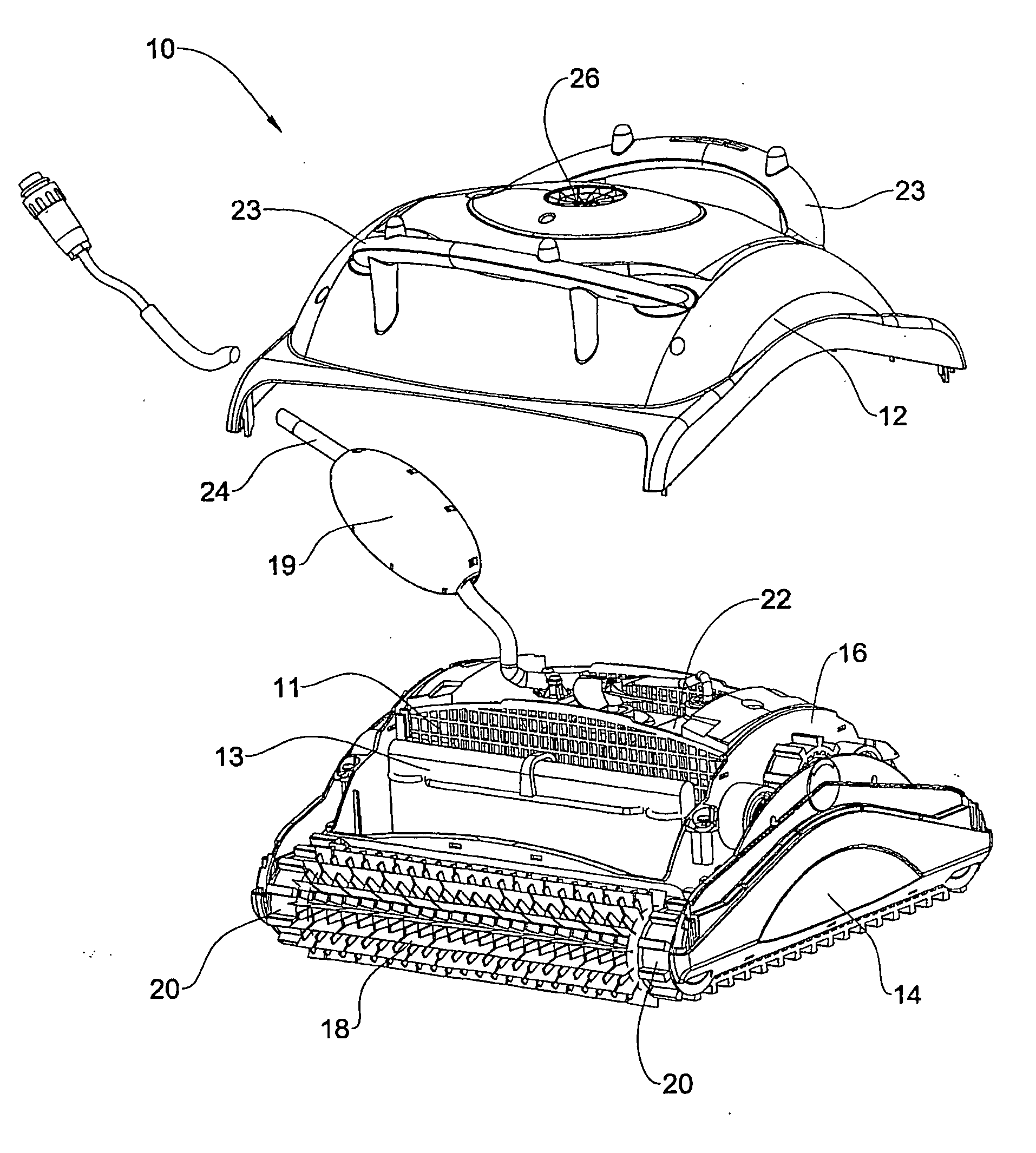
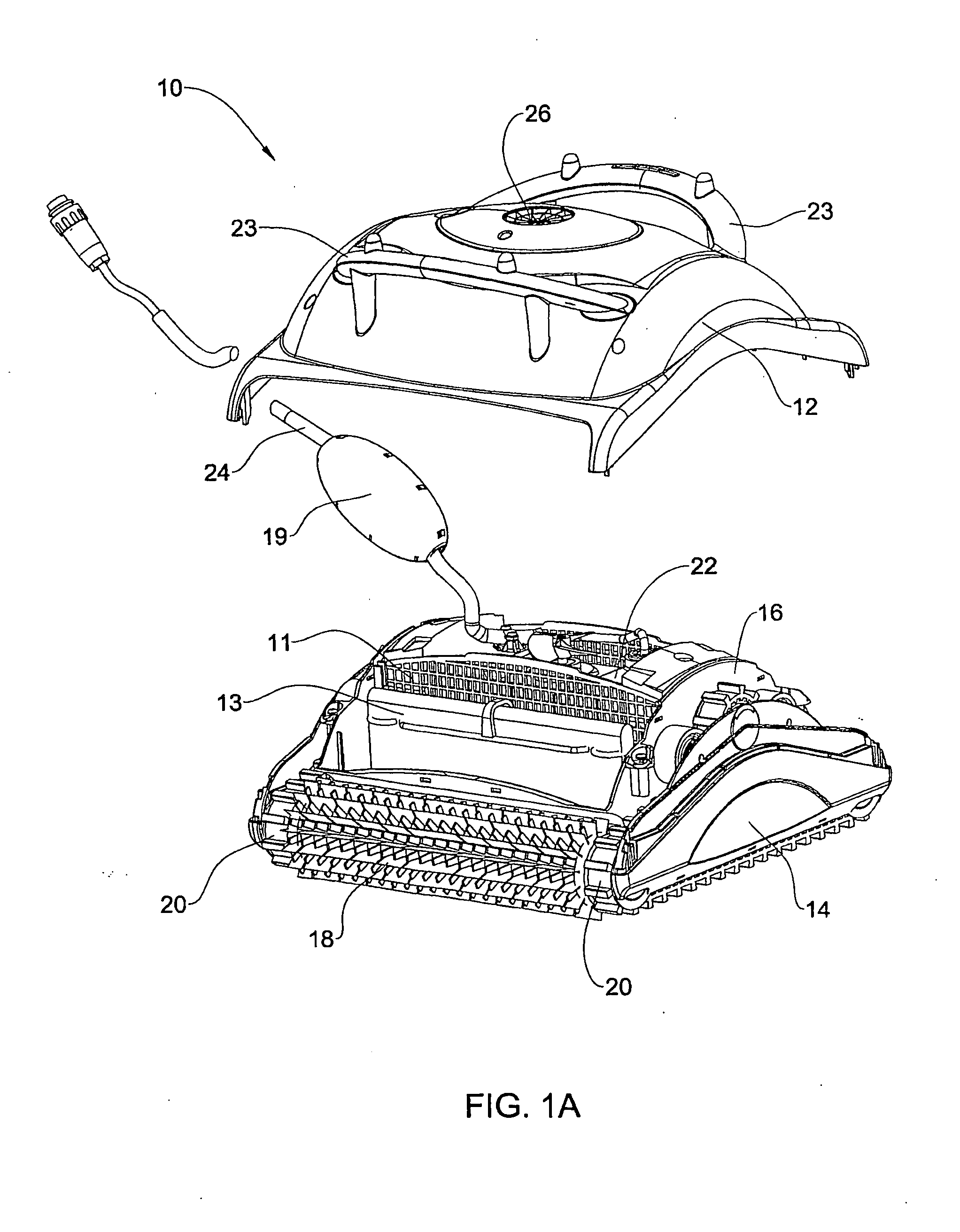
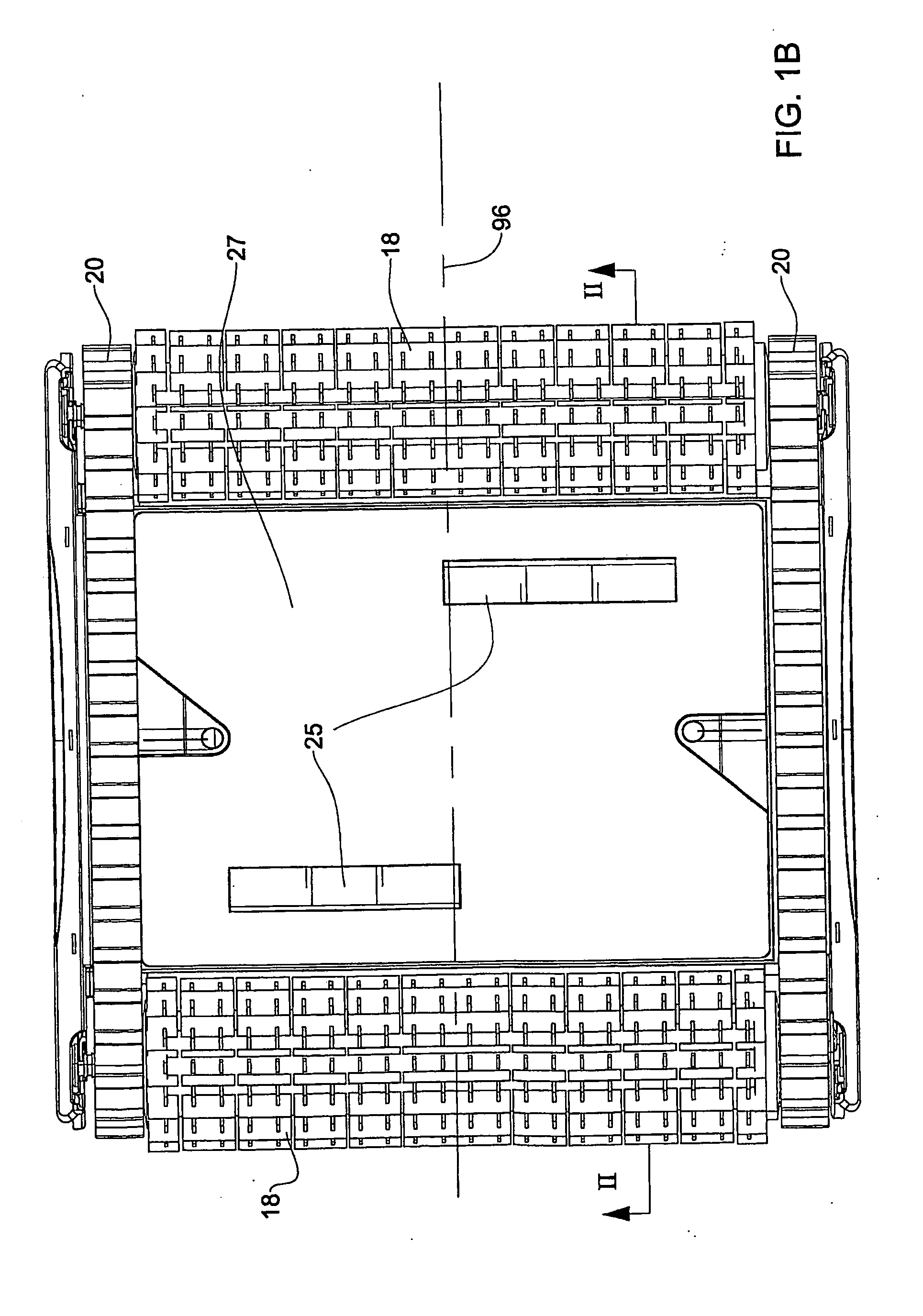
[0052]As seen in FIGS. 1A, 1B and 2, there is provided a pool cleaning robot 10, in accordance with one embodiment of the present invention, which comprises a housing including an internal frame 16 (seen in more detail in FIG. 2), side panels 14, a bottom panel 27 and a cover 12, and mounted in the internal frame an internal module 22 (seen in more detail in FIGS. 7A and 7B), a filter screen 11, a filter unit with a filter bag 13, front and rear brushwheels 18, and two tracks 20. The cover 12 comprises a pair of handles 23 and an outlet opening 26. The cover 12 and the side panels 14 are attached with screws to the internal frame 16. The robot further comprises a power cord 24 with a float 19 and inlets 25 formed in the bottom panel 27.

[0053]As seen in FIG. 2, the internal frame 16 is integral and comprises two sidewalls 28 and two outwardly curved front / back walls 30 (since the robot is bidirectional, each of these walls may be alternately a front wall and a back wall, depending on...


PUM


Abstract

A pool cleaning robot adapted for climbing a sidewall of a pool and comprising a bottom and two side panels. The robot is adapted for moving in a direction substantially parallel to the side panels. At least one of the side panels comprises a freely-rotating roller located adjacent to the bottom of the robot.

Description

[0001]This application is a Continuation Application, and claims the benefit of, PCT application number PCT / IL2006 / 000901, filed on Aug. 3, 2006, which is a Continuation-in-Part Application of U.S. application Ser. No. 11 / 196,737, filed on Aug. 4, 2005.FIELD OF THE INVENTION[0002]This invention relates to devices for cleaning swimming pools, basins, and the like. More particularly, the invention relates to an automatic self-propelled cleaning robot.BACKGROUND OF THE INVENTION[0003]Pool cleaning robots which automatically scan the floor and / or sidewalls of a swimming pool are well known in the art. These units are powered internally, by one or more battery packs, or externally, by way of a power cable. A robot of this type typically comprises a drive motor, a pump motor with an impeller, a filter, brushwheels, and a track. All of these components are contained within a housing. The housing comprises inlets at the bottom, and an outlet at the top. The robot comprises several sections,...

Claims


Application Information

Patent Timeline
Patent Type & Authority Applications(United States)
IPC IPC(8): E04H4/16
CPCE04H4/1654
Inventor GARTI, EFRAIM
Owner MAYTRONICS LTD
Why Eureka
Try Eureka