
Electrode holder

a technology of electrode holders and electrodes, applied in the direction of electrical equipment, arc welding equipment, electric discharge heating, etc., can solve the problems of affecting the performance affecting the safety of the electrode holders, so as to reduce the possibility of electric hazards

Inactive Publication Date: 2008-06-05
DAZCOR IP
View PDF2 Cites 92 Cited by
  • Summary
  • Abstract
  • Description
  • Claims
  • Application Information

AI Technical Summary

Benefits of technology

[0011]It is an object of the invention to provide an electrode holder which may overcome at least some of the above-mentioned disadvantages or provide a useful or commercial choice.
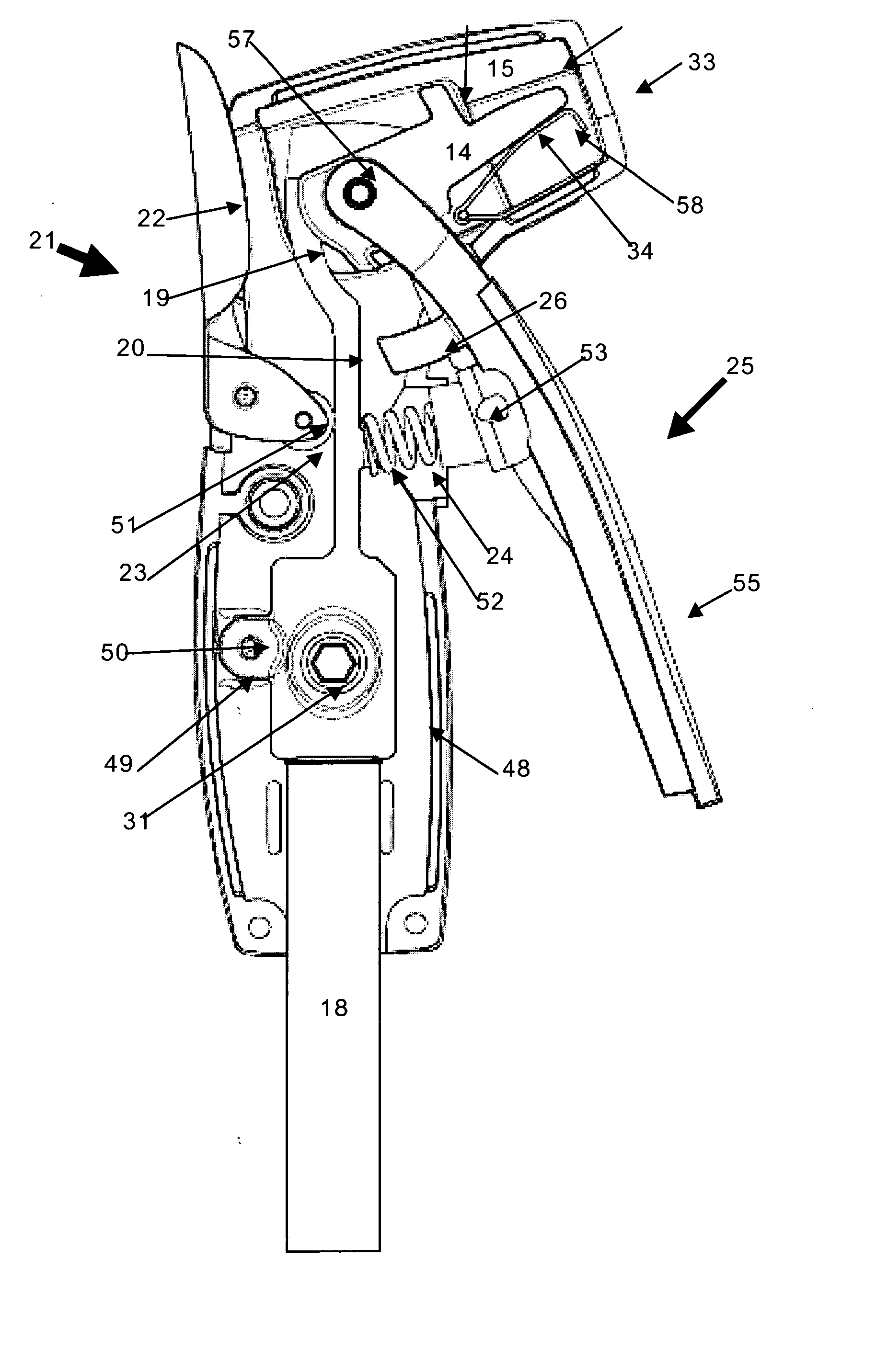
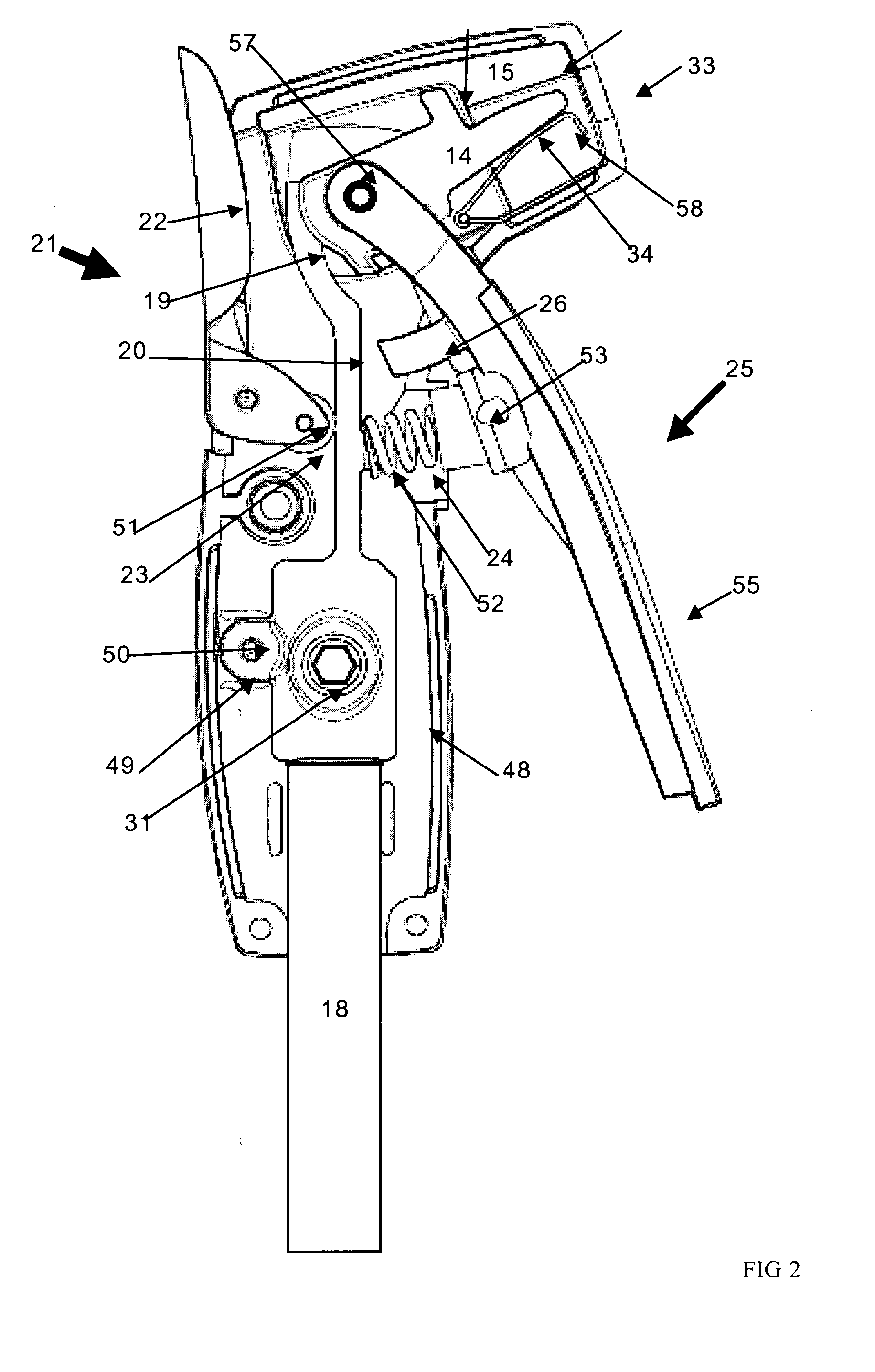
[0038]The rigid conducting element (and particularly the upper portion) can move between a first position where the rigid conducting element engages with the moving jaw and a second position where the rigid conducting element does not engage with the moving jaw. Suitably, the rigid conducting element can pivot between these two positions. Therefore, the rigid conducting element may be attached to a pivot pin. The pivot pin may extend through an opening on a small lug that extends from the lower power cable attachment portion an example of which is illustrated least in FIG. 2. By having the pivot pin positioned adjacent the cable attachment portion the degree of pivoting movement at the cable attachment portion is minimal (typically only a few millimetres) and therefore does not cause unnecessary wear and tear between the power cable attachment to the cable attachment portion.
[0050]In a broad form the invention comprises a hand held electrode holder having a power on / off switch on the handle of the electrode holder and a actuator (e.g. a trigger) to open the clamping jaws that clamp the electrode. The holder has internal parts which operate such that the actuator cannot open the clamping jaws while the switch is in the power on position thereby reducing the possibility of an electric hazard when changing electrodes.

Problems solved by technology

The electrode is a consumable and must be replaced periodically and there is always a hazard in doing so as it is essential that the electrode is isolated from the power prior to removal.
A hazardous situation can occur if an operator releases the electrode without initially switching off the power, or touches the electrode accidentally.
However, my earlier designs still suffered from some disadvantages including complexity of componentry, and sometimes a somewhat awkward arrangement of the power isolating switch.

Method used


Image

  • Electrode holder
  • Electrode holder
  • Electrode holder

Examples


Embodiment Construction

Preferred Embodiment of the Invention

FIGS. 1-6

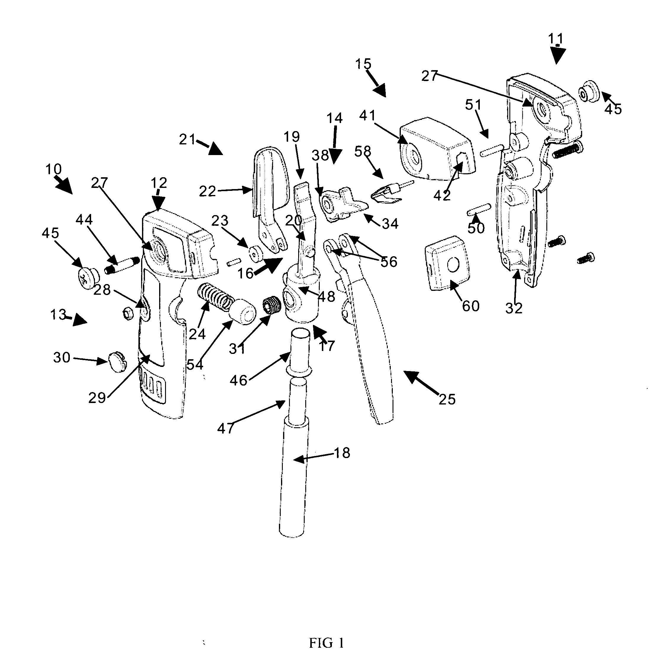
[0068]Referring to the drawings and initially to FIG. 1, there is illustrated an exploded view of the electrode holder which generally comprises the following components:

[0069]1. an outer housing 10, 11 having a head portion 12 and a handle portion 13,

[0070]2. an electrode clamping assembly in the head portion and which comprises a moving jaw 14 and a fixed jaw 15, the moving jaw being movable between an electrode clamping position and a release position,

[0071]3. a rigid conducting element 16 having a lower power cable attachment portion 17 attachable directly or indirectly to power cable 18, an upper portion 19 electrically engageable with the moving jaw, and a track portion 20, the rigid conducting element able to move between a power on position where the upper portion electrically engages with the moving jaw to provide power to the electrode and a power off position where the upper portion is in an electrically isolating position rel...


PUM

PropertyMeasurementUnit
Poweraaaaaaaaaa

Abstract

A hand held electrode holder has a power on / off switch on the handle of the electrode holder and a trigger to open the clamping jaws that clamp the electrode. The holder has internal parts which operate such that the trigger cannot open the clamping jaws while the switch is in the power on position thereby reducing the possibility of an electric hazard when changing electrodes.

Description

CROSS REFERENCE TO RELATED APPLICATION(S)[0001]The present application is a continuation-in-part of application Ser. No. 10 / 544,703, filed Aug. 5, 2005.BACKGROUND OF THE INVENTION[0002]This invention is directed to an electrode holder of the type used for welding, air arc gouging, thermal lancing etc, and which contains an isolating switch and an electrode locking arrangement which is associated with the isolating switch such that operation of the isolating switch permits removal of the electrode from the electrode holder.[0003]In the field of welding there is provided an apparatus which contains an electrode and where the electrode is held in a holder, the holder typically being handheld by an operator. The electrode is a consumable and must be replaced periodically and there is always a hazard in doing so as it is essential that the electrode is isolated from the power prior to removal. In some situations, the electrode must be isolated from the power source when not in use. The h...

Claims


Application Information

Patent Timeline
IPC IPC(8): B23K9/28
CPCB23K9/28
Inventor SCHNEIDER, DARRYL DOUGLAS
Owner DAZCOR IP
Learn More