Power Line Communication System

a communication system and power line technology, applied in the field of power line communication system, can solve the problems of increased cost, burden on users, and disadvantages of the operating state of the instrument of which power is reduced, and achieve the effect of reducing cost and burden

Inactive Publication Date: 2008-06-05
FUNAI ELECTRIC CO LTD
View PDF5 Cites 15 Cited by
  • Summary
  • Abstract
  • Description
  • Claims
  • Application Information

AI Technical Summary

Benefits of technology

[0010]It is an object of the present invention to reduce the cost and the burden which are required in order to construct the power line communication system for transmitting or receiving the information among the plurality of electronic instruments interconnected through the power line, by applying the remote activation system for activating the electronic instruments by such a remote operation to the power line communication system.

Problems solved by technology

In a power control system in which a plurality of electric instruments are networked by using a power line, and the overall power consumptions are controlled within a rated capacity, by deciding an electric instrument of which power is reducible in real time in response to operating states of the electric instruments, an occurrence of a disadvantage in the operating state of the instrument of which power is reduced, is prevented.
However, heretofore, in order to realize the remote activation system as described above, because it is necessary to construct the wireless LAN system, there were some problems that the cost is increased and that a burden is imposed on a user.

Method used


Image

  • Power Line Communication System
  • Power Line Communication System
  • Power Line Communication System

Examples


embodiment 1

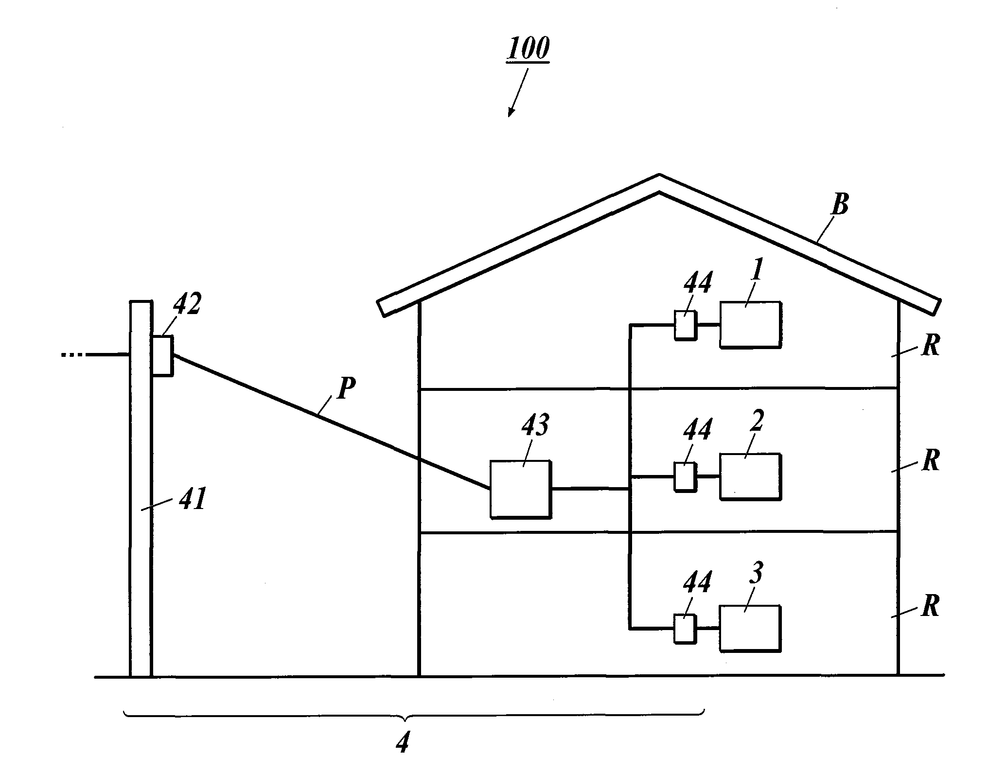
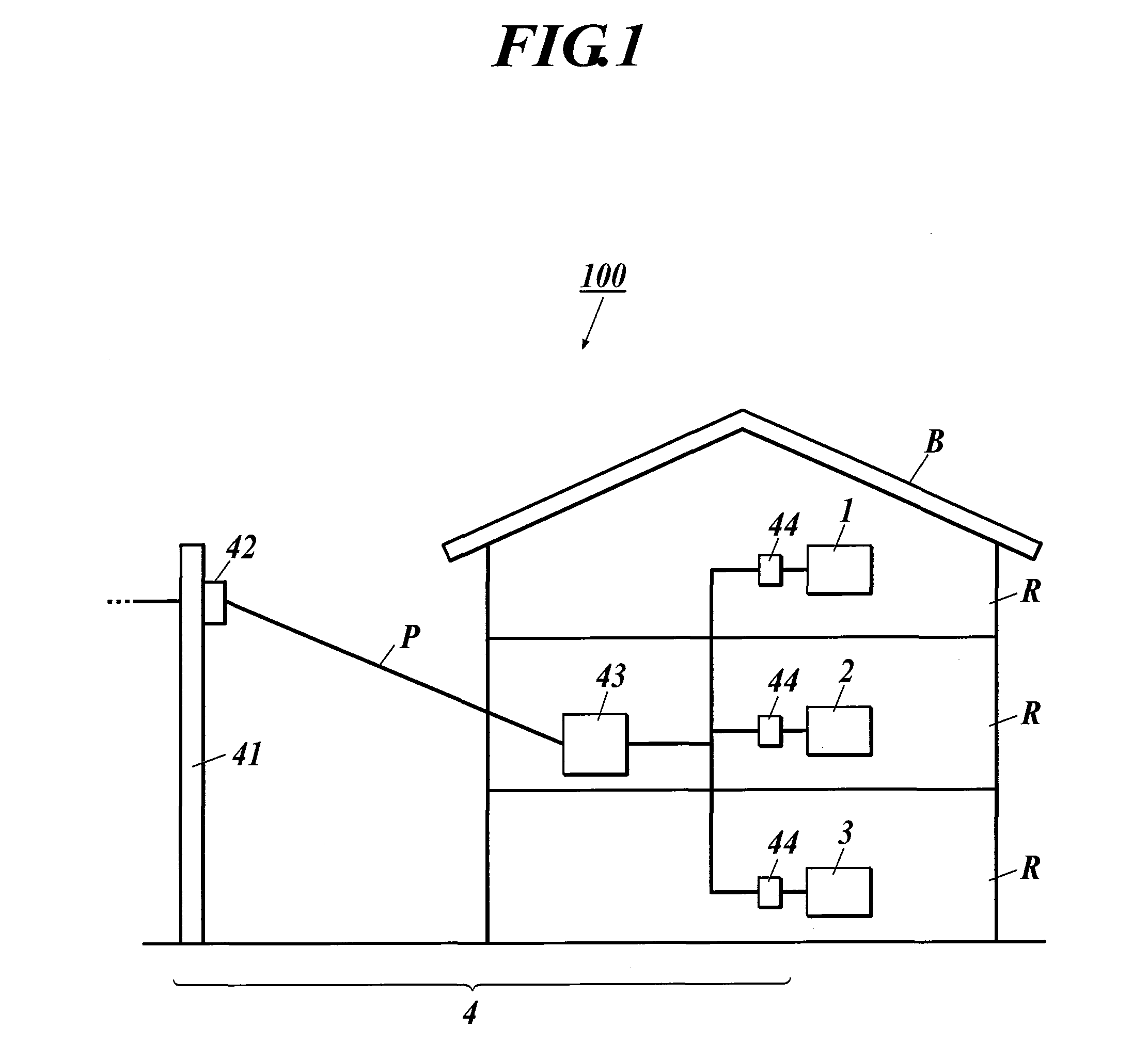
[0055]First, while referring to FIGS. 1 to 5, a description will be made of a power line communication system 100 of Embodiment 1 to which the present invention is applied. FIG. 1 is a view showing an entire configuration of the power line communication system 100 in Embodiment 1.

[0056]For example, as shown in FIG. 1, the power line communication system 100 of Embodiment 1 is a network realized in a house B. A server apparatus 1 as a first electronic instrument, a first client terminal apparatus 2 as a second electronic instrument and a second client terminal apparatus 3 as a third electronic instrument, which are provided in each room R, are connected through a power communication line 4 as a communication line using a power line P.

[0057]For example, the first client terminal apparatus 2 is a reproduction apparatus or the like that reproduces information such as video / audio data and transmits the reproduced video / audio data to the second client terminal apparatus 3 through the serv...

embodiment 2

[0153]Next, while referring to FIGS. 7 to 10, a description will be made of a power line communication system 200 of Embodiment 2 to which the present invention is applied.

[0154]Note that, in the following description, the same reference numerals are assigned to the same elements as those in Embodiment 1, and a description thereof will be omitted.

[0155]For example, as shown in FIG. 7, the power line communication system 200 of Embodiment 2 is a network realized in the house B. In the power line communication system 200, a server apparatus 5 as a first electronic instrument and a client terminal apparatus 6 as a second electronic instrument, which are provided in each room R, are connected through the power communication line 4 as the communication line using the power line P.

[0156]Here, in the power line communication system 200 of Embodiment 2, when the server apparatus 5 is turned on based on a key operation of a power-on key 121c in the key operation unit 121, the client terminal...


PUM


Abstract

A power line communication system includes: a first electronic instrument and a second electronic instrument, wherein information is received or transmitted between the first electronic instrument and the second electronic instrument which are connected through a communication line using a power line, wherein the first electronic instrument comprises: a key operation unit for accepting a key operation performed by a user; and a transmission unit for transmitting a power-on request signal for requesting the second electronic instrument to be turned on, to the second electronic instrument through the power line based on the key operation in the key operation unit, and the second electronic instrument comprises: a reception unit for receiving the power-on request signal transmitted from the first electronic instrument through the power line; and a power-on control unit for turning on the second electronic instrument based on the power-on request signal received by the reception unit.

Description

BACKGROUND OF THE INVENTION[0001]1. Field of the Invention[0002]The present invention relates to a power line communication system for transmitting and receiving information through a power line among a plurality of electronic instruments.[0003]2. Description of the Related Art[0004]Heretofore, there has been known a technology for power line communications (PLC) for transferring information by superimposing a high-frequency communication signal on a low frequency for supplying power.[0005]As the technology of the power line communications, for example, in Japanese Patent Application Laid-Open Publication No. 2001-145262, the following technology is disclosed. In a power control system in which a plurality of electric instruments are networked by using a power line, and the overall power consumptions are controlled within a rated capacity, by deciding an electric instrument of which power is reducible in real time in response to operating states of the electric instruments, an occur...

Claims


Application Information

Patent Timeline
Patent Type & Authority Applications(United States)
IPC IPC(8): G05B11/01
CPCH02J13/0024H04B3/542H04B2203/5416Y02E60/7823Y04S40/122Y04S40/146Y02E60/7892H04B2203/5441H02J13/00009H02J13/00034Y02E60/00Y04S40/121
Inventor MATSUOKA, MASAYOSHI
Owner FUNAI ELECTRIC CO LTD
Why Eureka
Try Eureka