Flat Mobile Antenna System

a mobile antenna and antenna system technology, applied in the direction of antennas, antenna details, antenna couplings, etc., can solve the problems of increasing the height of the system, affecting the use of certain types of vehicles, and affecting the quality of the system, so as to reduce the uncertainty of the phases, reduce the height, and facilitate the effect of production

Inactive Publication Date: 2008-06-05
GILAT SATELLITE NETWORKS
View PDF4 Cites 7 Cited by
  • Summary
  • Abstract
  • Description
  • Claims
  • Application Information

AI Technical Summary

Benefits of technology

[0066]The advantages of the antenna system according to the invention are its simplified from a technological point of view structure, giving an opportunity for realization of a system with low height, easier and cheaper production. The leveling of the structure allowed the feeding lines to be distributed in height, providing closer placement of the neighboring rows of antenna elements, which is extremely critical for the tracking parameters. On the other hand, the possibilities are avoided for mutual influence between long sequentially fed parts from the feeding lines, which minimizes the uncertainty of the phases, mutual coupling, possibility for blindness effect, etc.

Problems solved by technology

Disadvantage of the known mobile antenna systems with combined electronic and mechanical tracking is that they have relatively big dimensions especially in height, what makes their use difficult on some types of vehicles, for instance passenger cars.
Another drawback of these systems is their complicated structure, ensuring the necessary parameters of the system, however, in turn, resulting in comparatively high price.
Disadvantage of the solution is the necessity of additional mechanical tilting in elevation plane leading to further increase of the height of the system.
Other similar solution is shown in U.S. Pat. No. 5,886,671, where fully electronic steering is realized, which makes the structure more complicated and more expensive.
Main drawback of such solution is the impossibility to build the system with low profile.

Method used


Image

  • Flat Mobile Antenna System
  • Flat Mobile Antenna System
  • Flat Mobile Antenna System

Examples


Embodiment Construction

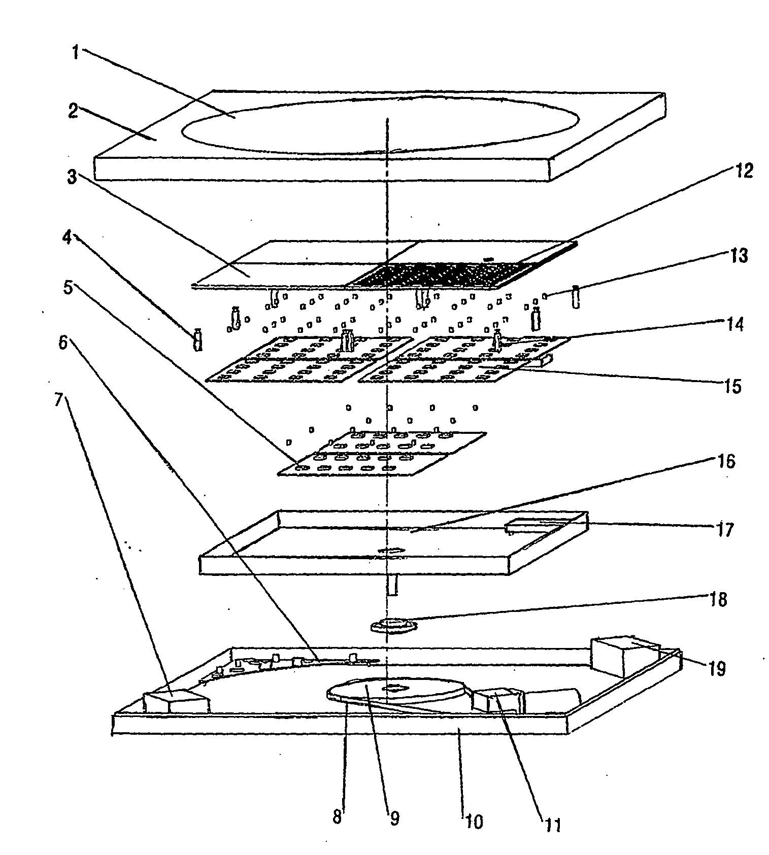
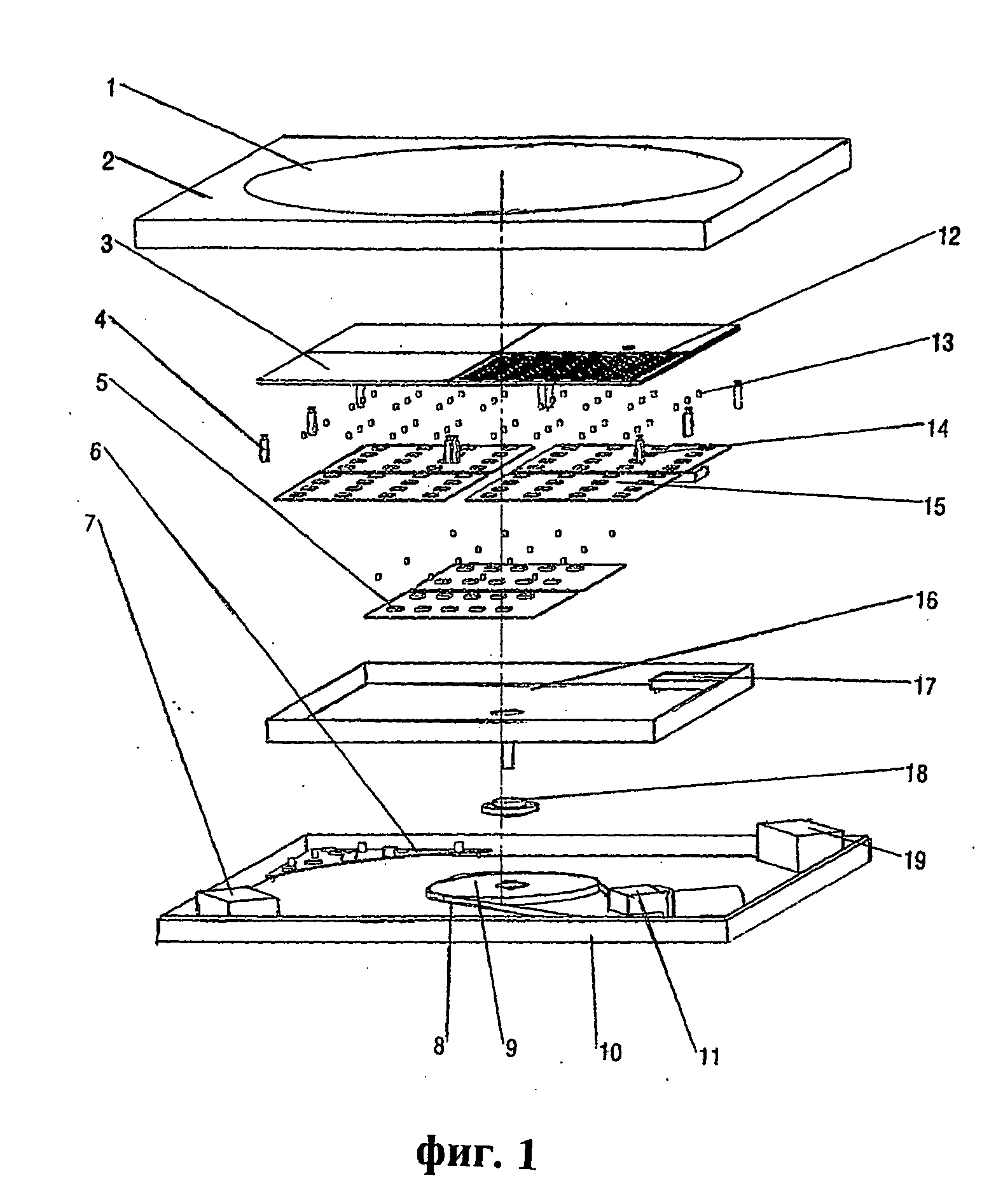
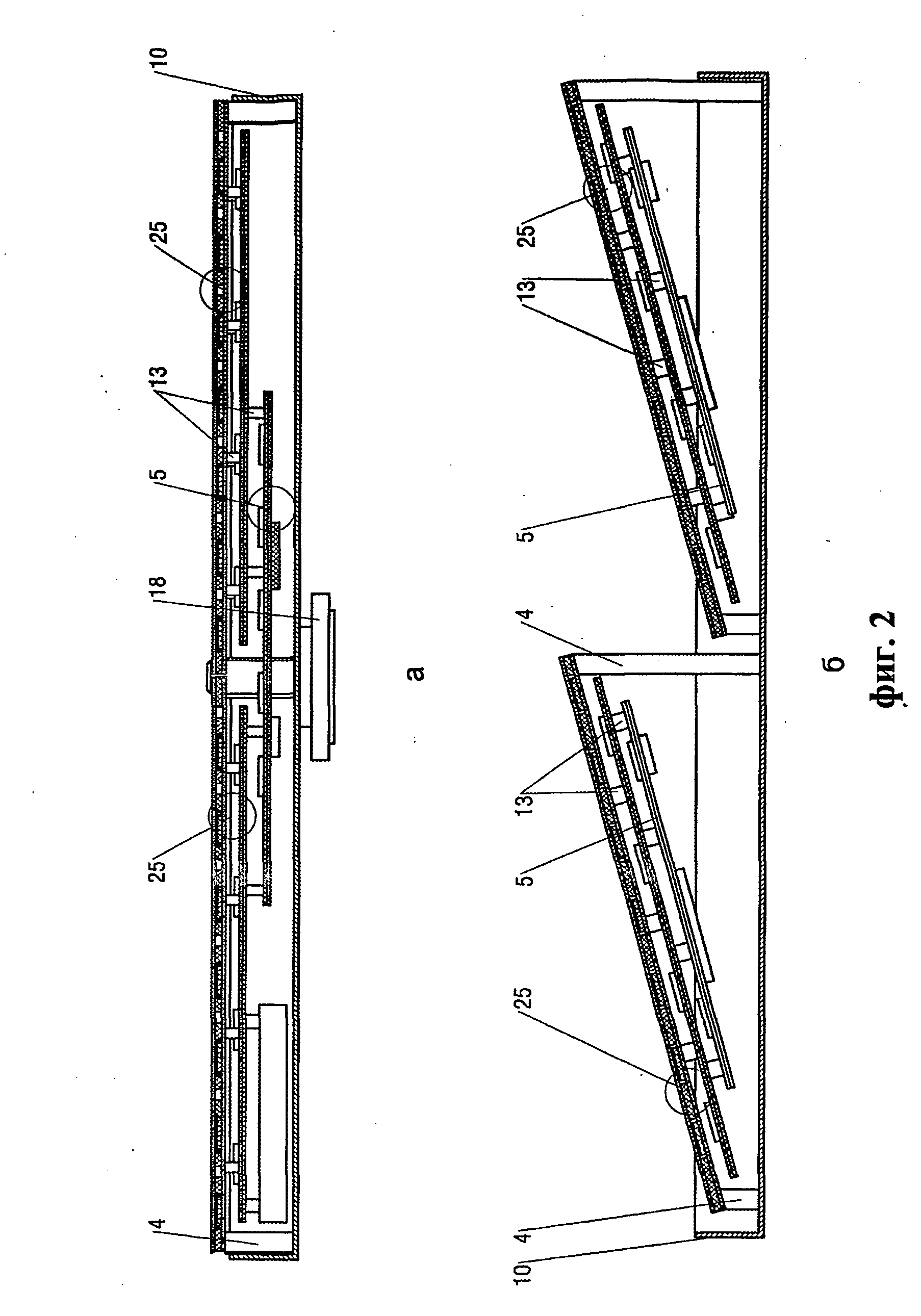
[0073]The Antenna system includes rotary and static parts. The static part is the box of the system, comprising bottom 10 (FIG. 1), cover 2, with radiotransparent part 1, microprocessor control unit 6, motor with motor controller 11, belt gear 8, providing the necessary properties of the driving, power supply module 7 and satellite recognition module 19. The rotary part is a steerable phased array, which is rotated in the horizontal plane around its geometric center, while with the steering of the rotation the azimuth tracking of the receiving signal is provided. The elevation tracking is provided electronically. The tracking is done according to a special algorithm, using information about the strength of the receiving signal and the spatial movement of the antenna array. The rotary part is comprised of a plurality of layered structures 3,5,15 (FIG. 1), building separate levels and including microstrip antenna elements 12, feeding transmission lines 20 (FIG. 4), which carry and com...


PUM


Abstract

Mobile antenna system comprising rotary part by azimuth, which is an electronically steered in elevation phase array antenna, comprising: plurality of (multi)layered structures, placed at certain levels, said structures include microstrip antenna elements (12), feeding lines (20), which properly combined and guide the electromagnetic energy, forming the necessary phase and amplitude distribution over the antenna elements, a plurality of electronic modules (28) providing amplification, phase change, frequency conversion and steering of the received signal, power supply and control circuits for the same electronic modules; a plurality of vertical transitions (13), providing the passing of the electromagnetic energy between the layered structures from different levels; frequency converting device and rotary joint (18), passing the received signal, the power supply and control circuits to the static part; sensors detecting the spatial movement of the system, and power supply and control units; static part, comprising bottom (10), cover (2) with radiotransparent part (1), mechanical supports, motor (11), gear, plurality of electronic modules (19, 6, 7).

Description

[0001]This application is a U.S. National Stage application of co-pending PCT application PCT / BG2004 / 000003 filed Mar. 8, 2004, which was published in English under PCT Article 21(2) on Sep. 16, 2004, and which claims the priority of Bulgarian Patent Application No. 107620, filed Mar. 6, 2003. These applications are incorporated herein by reference in their entireties.FIELD OF THE INVENTION[0002]The presented invention concerns a flat antenna system, which could be used on moving vehicles and platforms to receive TV, Internet and other communication signals broadcasted from satellites.PRIOR ART[0003]The known mobile satellite antenna systems are with mechanical, electronic or combined—electromechanical tracking. The systems with purely mechanical tracking use directed antennas which are rotated mechanically toward the satellite direction, while these with electronic tracking form a directional radiating pattern in the needed direction. A suitable variant is to combine the mechanical...

Claims


Application Information

Patent Timeline
Patent Type & Authority Applications(United States)
IPC IPC(8): H01Q3/04H01Q3/08H01Q3/26H01Q21/06H01Q3/30
CPCH01Q3/08H01Q3/26H01Q3/04H01Q21/065H01Q3/30H01Q21/06
Inventor BOYANOV, VICTORMARINOV, BORISLAVKAMENOPOLSKI, STANIMIRPOPOVA, MARIYASLAVKOV, IVAYLOLYUBENOV, GEORGITRAYKOV, ROSSEN
Owner GILAT SATELLITE NETWORKS
Why Eureka
Try Eureka