Frame rate conversion apparatus for video signal and display apparatus
a conversion apparatus and video signal technology, applied in the field of frame rate conversion technique, can solve the problems of lowering the quality of video, and achieve the effect of suppressing the lowering of the image quality of a video and reducing the calculation process amoun
- Summary
- Abstract
- Description
- Claims
- Application Information
AI Technical Summary
Benefits of technology
Problems solved by technology
Method used
Image
Examples
embodiment 1
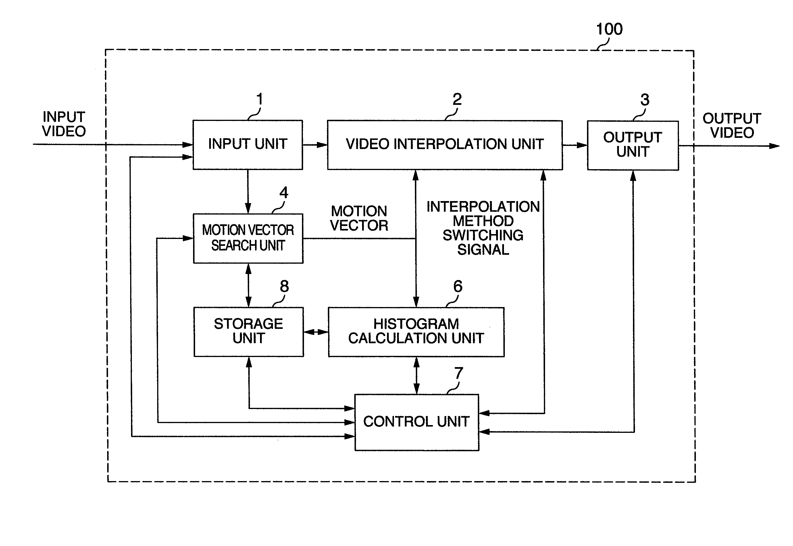
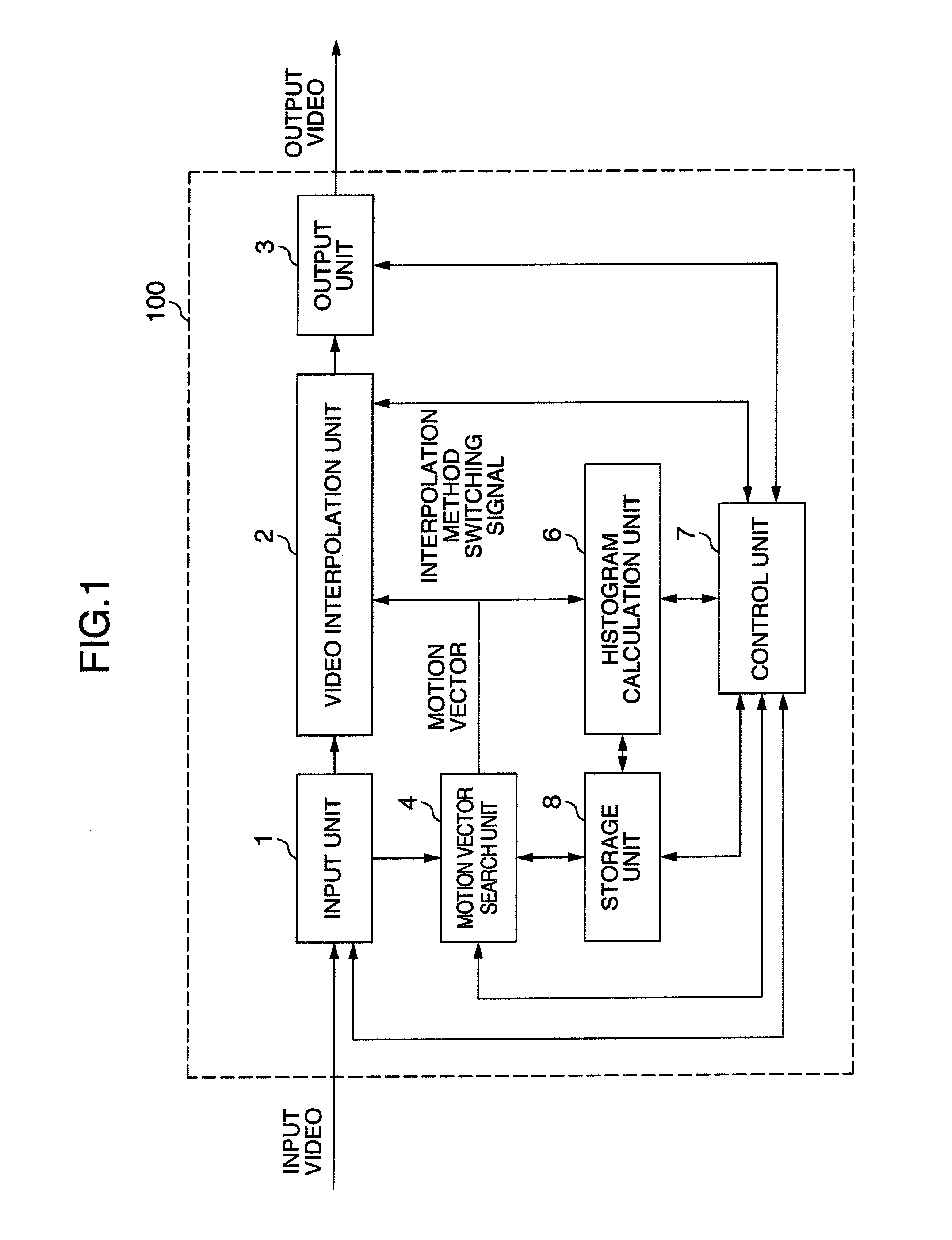
[0028]Firstly, explanation will be given on a first embodiment of the present invention with reference to the drawings. FIG. 1 shows an example of a block diagram of a motion correction type frame rate conversion apparatus 100 according to the first embodiment of the present invention.
[0029]The frame rate conversion apparatus 100, for example, includes: an input unit 1 for inputting an input video signal; a video interpolation unit 2 for changing the frame rate of the input video signal by performing an interpolation frame generation process concerning the input video signal for the input video signal by using a plurality of methods; an output unit 3 for outputting the video signal for which the frame rate has been changed, as an output video signal; a motion vector search unit 4 for searching a motion vector for the input video signal to be inputted to the input unit 1; a histogram calculation unit 6 performing a histogram calculation process on the motion vector searched by the mo...
embodiment 2
[0103]Next, explanation will be given on a second embodiment of the present invention with reference to the drawings. The frame rate conversion apparatus according to the second embodiment is identical to the frame rate conversion apparatus according to the first embodiment except for that a predetermined period is set for the switching limit period concerning the switching judgment process or the judgment process performed by the control unit 7. Alternatively, in the frame rate conversion apparatus of FIG. 1, the judgment process of the control unit 7 in the second embodiment has a hysteresis.
[0104]Referring to FIG. 6, explanation will be given on an example of the judgment process. The graph shown at the top indicates a temporal transition 61 of the judgment parameter value explained in the first embodiment. As has been explained in the first embodiment, as the value increases, the interpolation process of video having a greater amount of motions is performed. The graphs shown at ...
embodiment 3
[0128]Next, explanation will be given on a third embodiment of the present invention with reference to the drawings. A frame rate conversion apparatus according to the third embodiment is identical to the frame rate conversion apparatus of the first or the second embodiment except for that other judgment reference information is used in the switching judgment process by the control unit 7.
[0129]For example, the control unit 7 in the third embodiment uses a judgment condition of row 30 stored in the judgment reference information 30 shown in FIG. 3. The data stored in row 36 of the judgment reference information 30 has a data name “acquired signal 1”, a data type “acquired signal condition”, and a data content “signal B contained”.
[0130]The control unit 7 uses the data stored in row 36 as the judgment reference. In this case, for example, the control unit 7 judges whether the input signal inputted to the input unit 1 of FIG. 2 contains “signal B”. If the input signal does not contain...
PUM
 Abstract
Description
Claims
Application Information
 - R&D
- Intellectual Property
- Life Sciences
- Materials
- Tech Scout
- Unparalleled Data Quality
- Higher Quality Content
- 60% Fewer Hallucinations
Browse by: Latest US Patents, China's latest patents, Technical Efficacy Thesaurus, Application Domain, Technology Topic, Popular Technical Reports.
© 2025 PatSnap. All rights reserved.Legal|Privacy policy|Modern Slavery Act Transparency Statement|Sitemap|About US| Contact US: help@patsnap.com


