Optical element having periodic structure and optical apparatus using the same
- Summary
- Abstract
- Description
- Claims
- Application Information
AI Technical Summary
Benefits of technology
Problems solved by technology
Method used
Image

Examples
embodiment 1
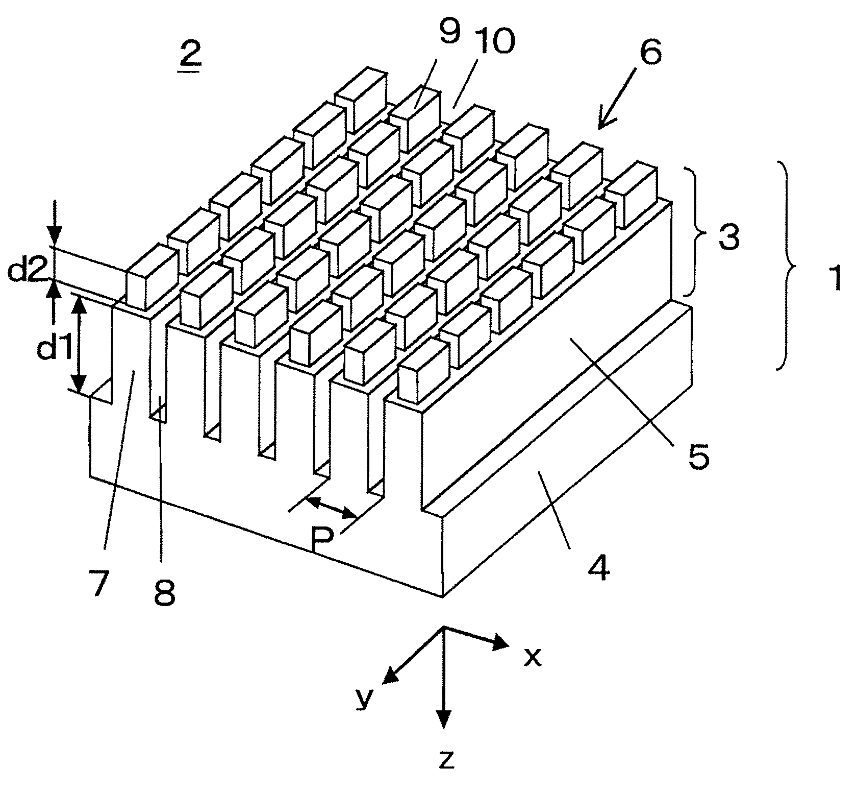
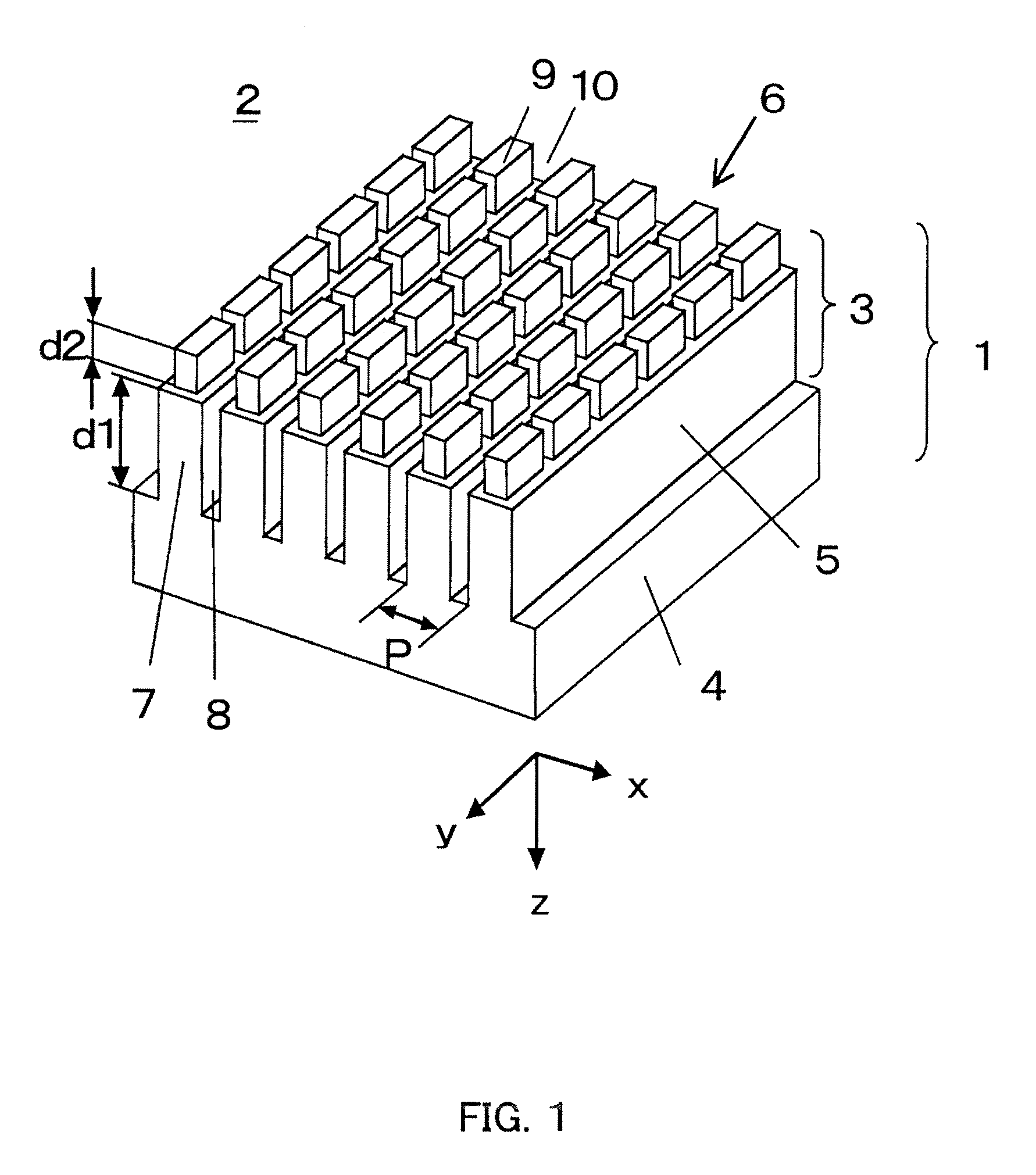
[0114]Referring to FIG. 1 and FIGS. 3A to 3C, a phase plate that is a design example as a first embodiment (Embodiment 1) of the present invention will be described in detail. In this embodiment, the phase plate is configured as shown in FIG. 1. In other words, the phase plate is constituted by the phase difference portion 5 having a one-dimensional periodic structure formed on the base portion 4 and the reflection-suppressing portion 6 having a two-dimensional periodic structure formed on the phase difference portion 5.
[0115]The phase plate of this embodiment is used as a quarter-wave plate for the image projection apparatus described above. This is also applied for the other embodiments described below.
[0116]The quarter-wave plate is optimized for a wavelength band (a wavelength band of incident light, that is, a use wavelength band) for each color because it is used for an optical path after color separation. Specifically, the quarter-wave plate for blue is optimized for a wavele...
embodiment 2
[0135]FIG. 6 and FIGS. 7A to 7C show the structure of the phase plate (quarter-wave plate) that is a second embodiment (Embodiment 2) of the present invention. FIG. 6 is a perspective view of the phase plate. FIGS. 7A and 7B are x-z and y-z cross sectional views of the phase plate shown in FIG. 6. FIG. 7C is a top view of the phase plate.
[0136]The phase plate of this embodiment has basically the same structure as that of Embodiment 1, and portions common to those in Embodiment 1 are designated with the same reference numerals as those in Embodiment 1. The phase plate of this embodiment is different from that of Embodiment 1 in that the periodic structure 3 and the base portion 4 are formed of materials different from each other.
[0137]FIGS. 8A to 8C show design parameters of the quarter-wave plate of this embodiment for each color. The periodic structure 3 is formed of Al2O3 (refractive index n=1.65), and the base portion 4 is formed of glass (refractive index n=1.52).
[0138]FIG. 9 sh...
embodiment 3
[0142]A design example of the phase plate (quarter-wave plate) as a third embodiment (Embodiment 3) of the present invention will be described, which has an improved phase difference characteristic as compared to that in Embodiment 2.
[0143]FIGS. 11A to 11C show design parameters of the quarter-wave plate of this embodiment for each color. FIG. 12 shows a phase difference characteristic thereof, and FIGS. 13A to 13C show a reflectance characteristic thereof.
[0144]As shown in FIG. 12, the phase difference characteristic is drastically improved as compared to that of Embodiment 2 so that a phase difference deviation is suppressed to equal to or less than 5 degrees in the use wavelength band. This characteristic shows a high performance that cannot be realized by the conventional quarter-wave plate.
[0145]As shown in FIGS. 13A to 13C, the reflectance characteristic is suppressed to equal to or less than 0.2% on average in the use wavelength band so that a good transmittance characteristi...
PUM
 Abstract
Description
Claims
Application Information
 - R&D
- Intellectual Property
- Life Sciences
- Materials
- Tech Scout
- Unparalleled Data Quality
- Higher Quality Content
- 60% Fewer Hallucinations
Browse by: Latest US Patents, China's latest patents, Technical Efficacy Thesaurus, Application Domain, Technology Topic, Popular Technical Reports.
© 2025 PatSnap. All rights reserved.Legal|Privacy policy|Modern Slavery Act Transparency Statement|Sitemap|About US| Contact US: help@patsnap.com