Method And Device For Fault Detection In Transformers Or Power Lines

a transformer and fault detection technology, applied in the direction of fault location, emergency protective circuit arrangement, instruments, etc., can solve the problems of widespread consequences, troublesome and costly for the electrical power supplier, etc., to achieve efficient detection of faults in power transformers and sensitive response

Active Publication Date: 2008-06-05
HITACHI ENERGY SWITZERLAND AG
View PDF8 Cites 48 Cited by
  • Summary
  • Abstract
  • Description
  • Claims
  • Application Information

AI Technical Summary

Benefits of technology

[0016]The invention according to U.S. Pat. No. 6,483,680 compares the phase angle difference between fundamental frequency (i.e. 50 Hz or 60 Hz) and second harmonic component (i.e. 100 Hz or 120 Hz) of the power transformer differential currents. More precisely, the invention compare complex ratio between these two phasors. This is done in order to determine if transformer is faulty during energizing (i.e. switch-on) of power transformer. This principle does not detect any internal or external fault during normal operating condition (i.e. through-load condition) of the power transformer, because it can only operate during power transformer energizing from one side. A typically power transformer is switched on just a couple of times per year (i.e. often just once for the yearly inspection). This means that the power transformer is energized and connected on at least two side for most of its life time (typically more than 95%). Therefore U.S. Pat. No. 6,483,680 has very limited use during this short time of power transformer energizing. Additionally this method typically can not detect small faults like turn-to-turn faults even during power transformer energizing.
[0017]The patent application WO02/334

Problems solved by technology

Faults in power transformers may lead to widespread consequences, both in the form of power failure for a large group of customers and in the form of that the faulty transformer has to be exchanged or at least repaired.
Both consequences are troublesome and costly for the supplier of the electrical power.
The consequences of unwanted disconnections of healthy equipment, such as power transformers, is also very costly.
In the worst case, the unwanted disconnections can result in wider black-outs.
When OLTC moves from one position to another, amplitude mismatch between power transformer winding currents will outcome causing a false differential current.
Known transformer differential relays are usually not sensitive enough for low-level internal faults, which may happen for example within a power transformer tank.
The most common weaknesses of a traditional power transformer differential protection are long operation delays in case of heavy internal faults followed by main CT saturation due to 2nd harmonic b

Method used


Image

  • Method And Device For  Fault Detection In Transformers Or Power Lines
  • Method And Device For  Fault Detection In Transformers Or Power Lines
  • Method And Device For  Fault Detection In Transformers Or Power Lines

Examples


Embodiment Construction

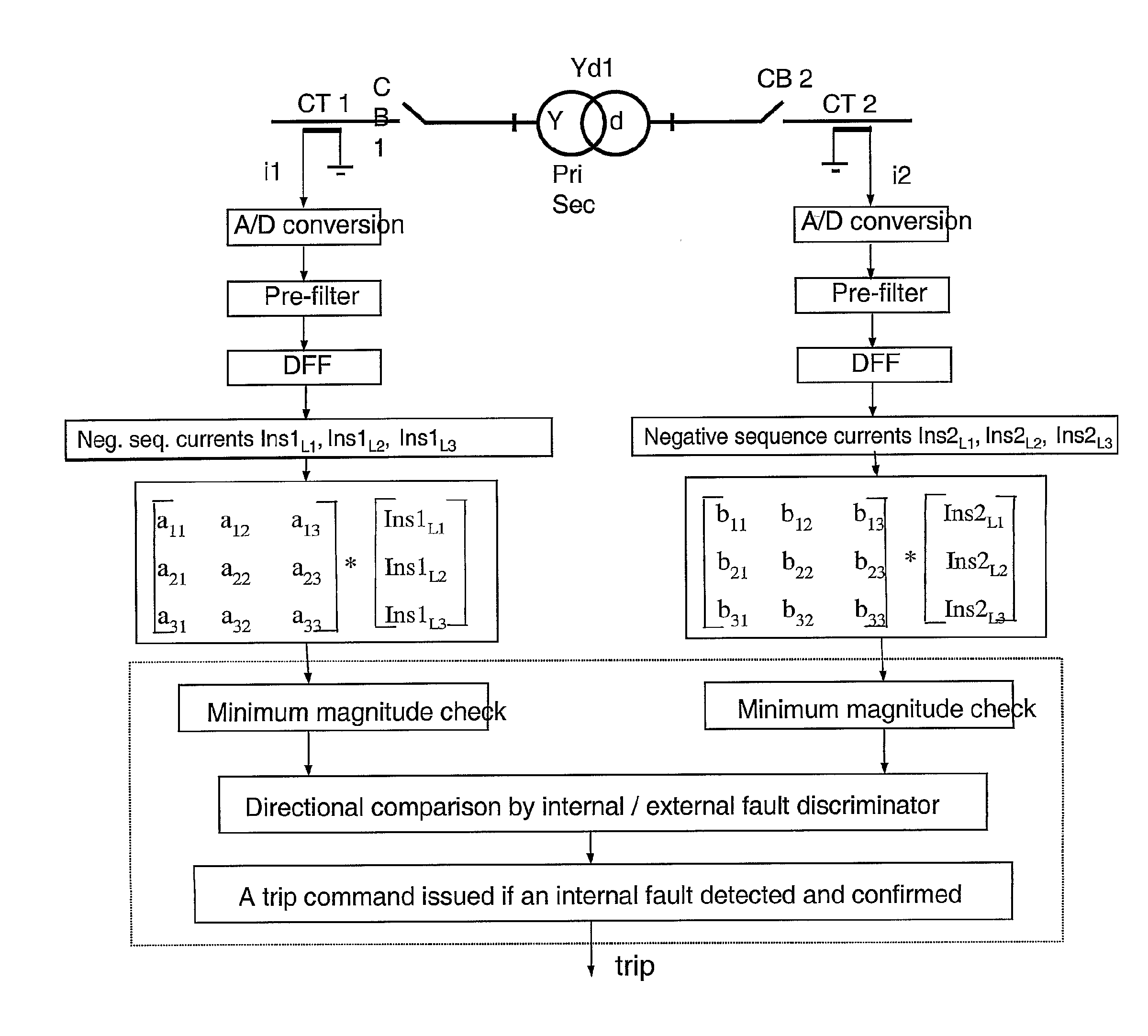
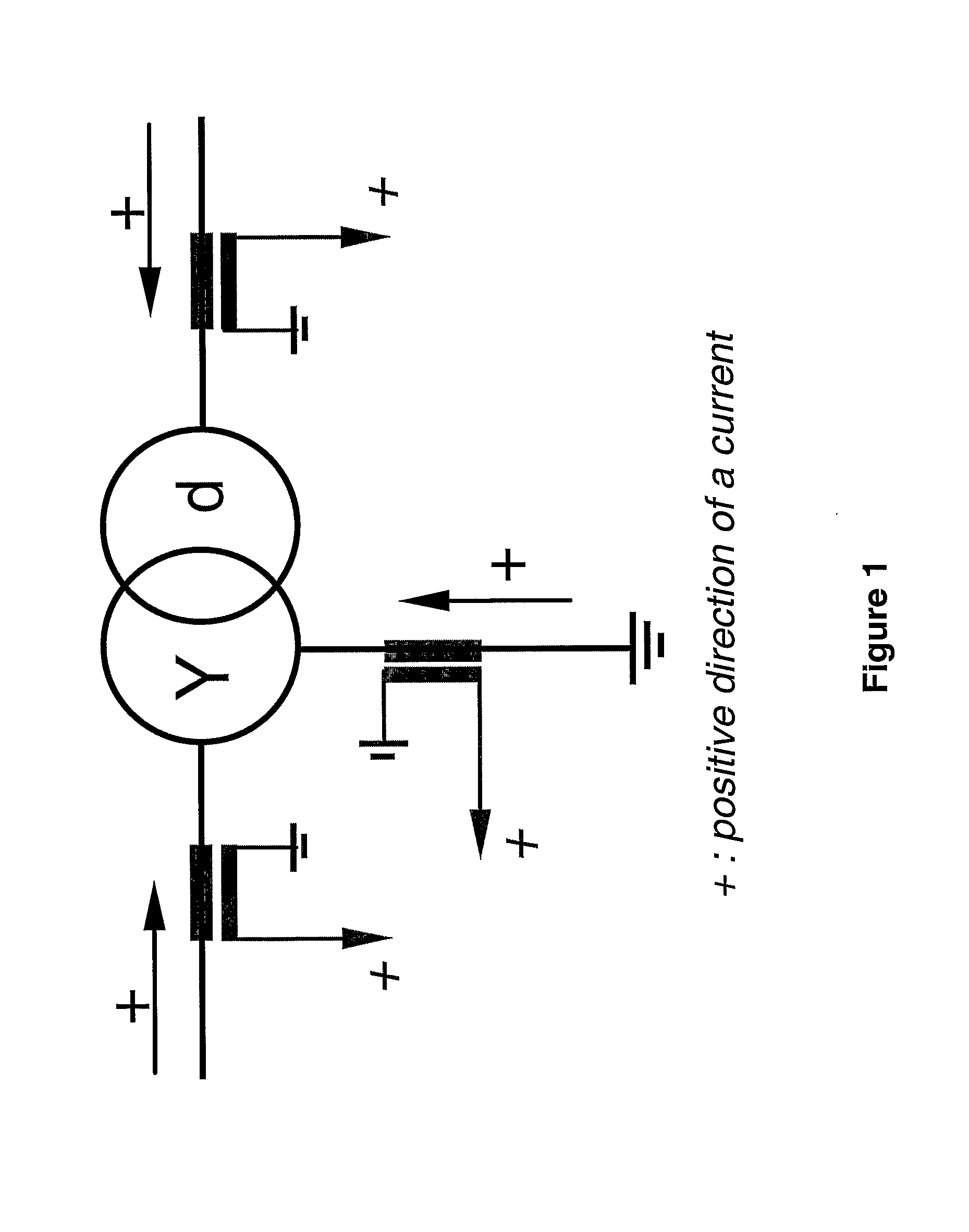
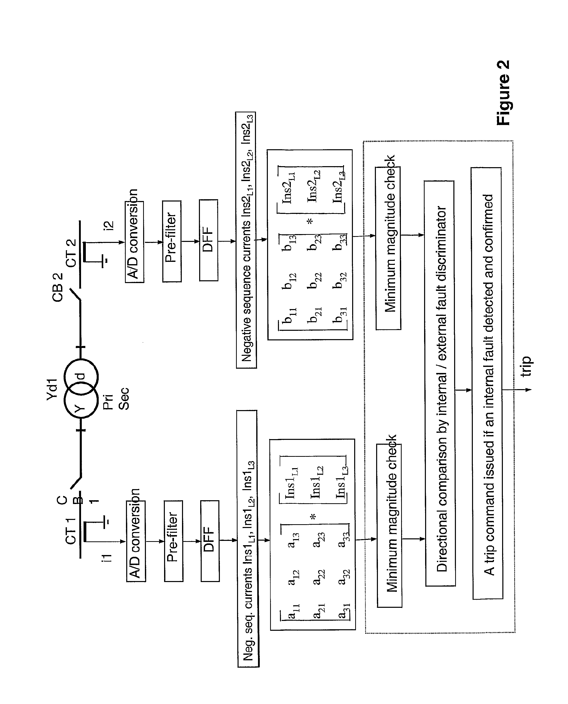
[0031]In FIG. 1 is illustrated an internal / external fault discriminator for protection of power transformers. The fault discriminator is made on pairs of components of the total negative sequence differential current. This discriminator may be implemented as a complement to the normal power transformer differential protection.

[0032]The internal / external fault discriminator determines the position of the source of the negative sequence fault currents with respect to the protected zone. If the source of the negative sequence fault currents is found to be outside the protection zone, then the fault is external.

[0033]If the source is found to be inside the zone, the fault is internal. The position of the negative sequence current source is determined as follows. At an internal fault, a degree of negative sequence differential current appears, and its two components (for a two-winding power transformer) are of the same direction, i.e. out of the protection zone.

[0034]At an external fault...


PUM


Abstract

A method for fault detection in a power transformer/autotransformer and/or interconnected power lines, which are within the zone protected by the differential protection, and particularly suitable for detecting turn-to-turn faults in power transformer/autotransformer windings. All individual instantaneous phase currents of the protected object are measured, individual phase currents as fundamental frequency phasors are calculated, the contributions of the individual protected object sides negative sequence currents to the total negative sequence differential current are calculated by compensating for the phase shift of an eventual power transformer within the protected zone, the relative positions of the compensated individual sides negative sequence currents in the complex plane are compared, in order to determine whether the source of the negative sequence currents, i.e. the fault position, is within the protected zone or outside of the protected zone, delimited with current transformer locations, the protected object is disconnected if determined that the source of the negative sequence currents is within the protected zone.

Description

TECHNICAL FIELD OF THE INVENTION[0001]This invention relates to a method and a device for improved protection of power transformers, autotransformers or power lines from the effects of internal faults by using an advanced differential protection system.BACKGROUND OF THE INVENTION[0002]Faults in power transformers may lead to widespread consequences, both in the form of power failure for a large group of customers and in the form of that the faulty transformer has to be exchanged or at least repaired. Both consequences are troublesome and costly for the supplier of the electrical power. The consequences of unwanted disconnections of healthy equipment, such as power transformers, is also very costly. In the worst case, the unwanted disconnections can result in wider black-outs.[0003]Protection devices such as differential relays normally safeguard power transformers. Differential relays typically have a minimum operating current level set to 30% of the protected power transformer curr...

Claims


Application Information

Patent Timeline
IPC IPC(8): H02H7/045G01R31/08H02H3/28
CPCH02H3/286G01R31/027H02H7/045G01R31/62
Inventor GAJIC, ZORANBRNCIC, IVO
Owner HITACHI ENERGY SWITZERLAND AG
Why Eureka
Try Eureka