Ionization device

Inactive Publication Date: 2008-06-05
KEYENCE
View PDF3 Cites 31 Cited by
  • Summary
  • Abstract
  • Description
  • Claims
  • Application Information

AI Technical Summary

Benefits of technology

[0012]The present invention is contrived in order to address to the above noted problems. A main object o

Problems solved by technology

However, providing separate discharge electrode bars for different areas with different numbers of required discharge electrodes poses problems such as requiring respective new designs and increase in cost.
However, the conventional discharge electrode bar is relatively heavy in weight because many metal components are used, and thus, a mechanical reinforcement is required to some extent in order to maintain strength at a coupling portion.
In order to maintain the strength, it is necessary to use such as an additional metal component for a coupling member, resulting in

Method used


Image

  • Ionization device
  • Ionization device
  • Ionization device

Examples


Example

First Embodiment

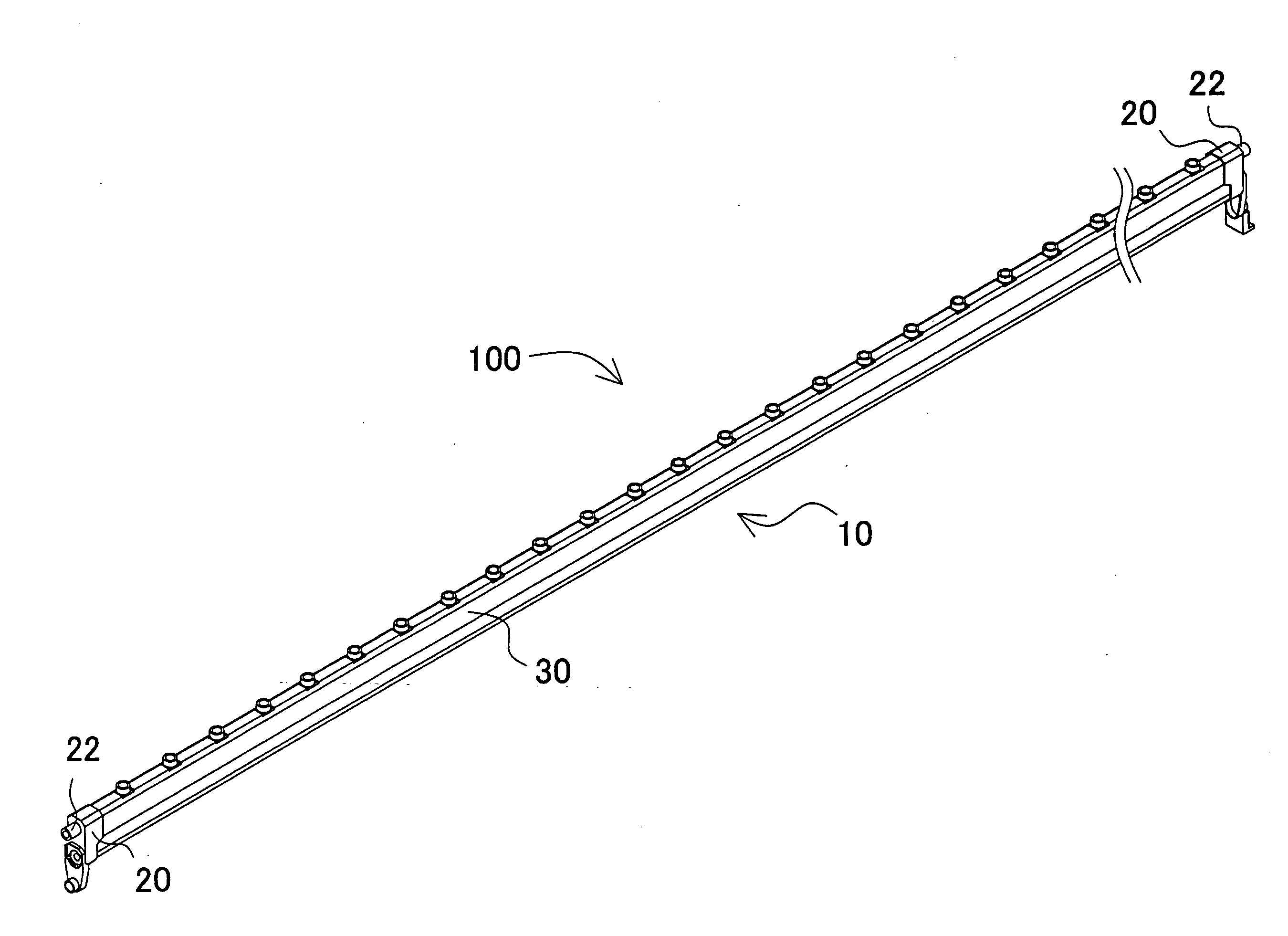
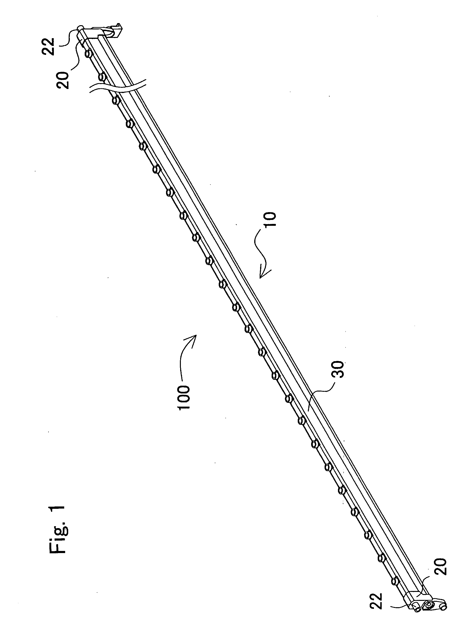
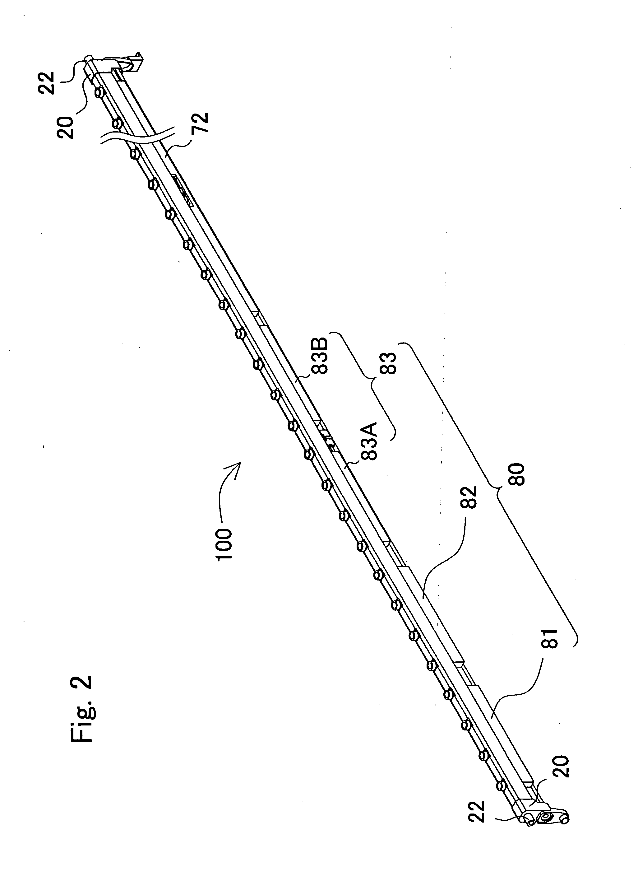
[0059]FIG. 1 to FIG. 4 show an ionization device 100 of a first embodiment according to the present invention. FIG. 1 shows a perspective view illustrating an appearance the ionization device 100 viewed obliquely. FIG. 2 shows a perspective view where a second casing is removed from the ionization device 100 as shown in FIG. 1. FIG. 3 shows a perspective view where a first casing, a covering portion and a reinforcement member 72 are removed from the ionization device as shown in FIG. 2. FIG. 4 shows a transverse sectional view of a main body. In these figures, objects are shown in a state in which a needle electrode 90 is on the upper side for explanation purpose, as opposed to a state they are actually used.

[0060]The ionization device 100 as shown in FIG. 1 constitutes a bar-type electricity remover having a controller built-in, so-called a discharge electrode bar. This ionization device 100 is provided with a main body casing 10 extended in an elongate shape, and s...


PUM


Abstract

An ionization device with increased rigidity of a coupling portion is provided. The ionization device includes a casing member for applying high voltage to each needle electrode; a coupling member for mechanically coupling a plurality of casing members in a longitudinal direction and electrically connecting high voltage plates of the respective casing members; and a elongated main body casing for housing a casing body constituted by coupling the plurality of casing members with the coupling member and the electrical circuit unit, the main body casing having the needle electrodes with a space from each other in the longitudinal direction and protruding outside. The main body casing integrally forms a space for arranging the casing body therein so as to be separated from a space for arranging the electrical circuit unit. With this configuration, the casing body to be applied with the high voltage is separated from the electrical circuit unit including a portion having low voltage, thereby avoiding unnecessary discharge.

Description

BACKGROUND OF THE INVENTION[0001]1. Field of the Invention[0002]The present invention relates to an ionization device for removing electricity charge in a charged body that is either positively or negatively charged.[0003]2. Description of the Related Art[0004]Static electricity removal (removal of electricity), such as cleanup in a clean room and prevention of static charge of suspended particulates, is performed in order to control static electricity in the air, and corona discharge ionization devices are widely used for removing electricity in a noncontact manner.[0005]A typical corona discharge electricity removing device causes corona discharge by applying either high voltage direct current or high voltage alternate current from a high voltage source to a needle electrode for discharge. FIG. 23 shows a schematic view of such an electricity removing device. The electricity removing device shown in this figure is provided with a discharge electrode 1 for causing corona discharge,...

Claims


Application Information

Patent Timeline
IPC IPC(8): H01T23/00
CPCH01T23/00H01T19/00
Inventor SHIMADA, TOMONORI
Owner KEYENCE
Why Eureka
Try Eureka