Fastening mechanism

a technology of fastening mechanism and heat sink, which is applied in the direction of cooling/ventilation/heating modification, semiconductor/solid-state device details, semiconductor devices, etc., can solve the problems of increasing heat generated by chips in operation, affecting the heat dissipation of chips, and loose sinks, so as to facilitate mounting operation and disassembly. , the effect of fastening the heat sink

Inactive Publication Date: 2008-06-05
INVENTEC CORP
View PDF7 Cites 2 Cited by
  • Summary
  • Abstract
  • Description
  • Claims
  • Application Information

AI Technical Summary

Benefits of technology

[0013]Compared to the prior art, the present invention discloses a fastening mechanism, wherein two bilaterally disposed snap-fit portions of the fastening mechanism are snapped to a circuit board, and a snap-fit force allows the body of the fastening mechanism to press on a h

Problems solved by technology

As a result, chips in operation generate an increasing amount of heat.
However, a conventional heat sink is typically fastened to a chip by means of thermally conductive tape or adhesive, though inefficiently; and the heat sink tends to loosen and thereby detach because of computer-induced vibration or when the computer is manually moved.
Nonetheless, with a small area of contact between the conventional fastener and a heat sink, no pressing force can be uniformly and consistently applied, and in consequence a chip and the heat sink cannot be pressed together evenly and tightly, an

Method used


Image

  • Fastening mechanism
  • Fastening mechanism
  • Fastening mechanism

Examples


Embodiment Construction

[0018]The following specific embodiment is provided to illustrate the present invention. Others ordinarily skilled in the art can readily gain an insight into other advantages and features of the present invention based on the contents disclosed in this specification.

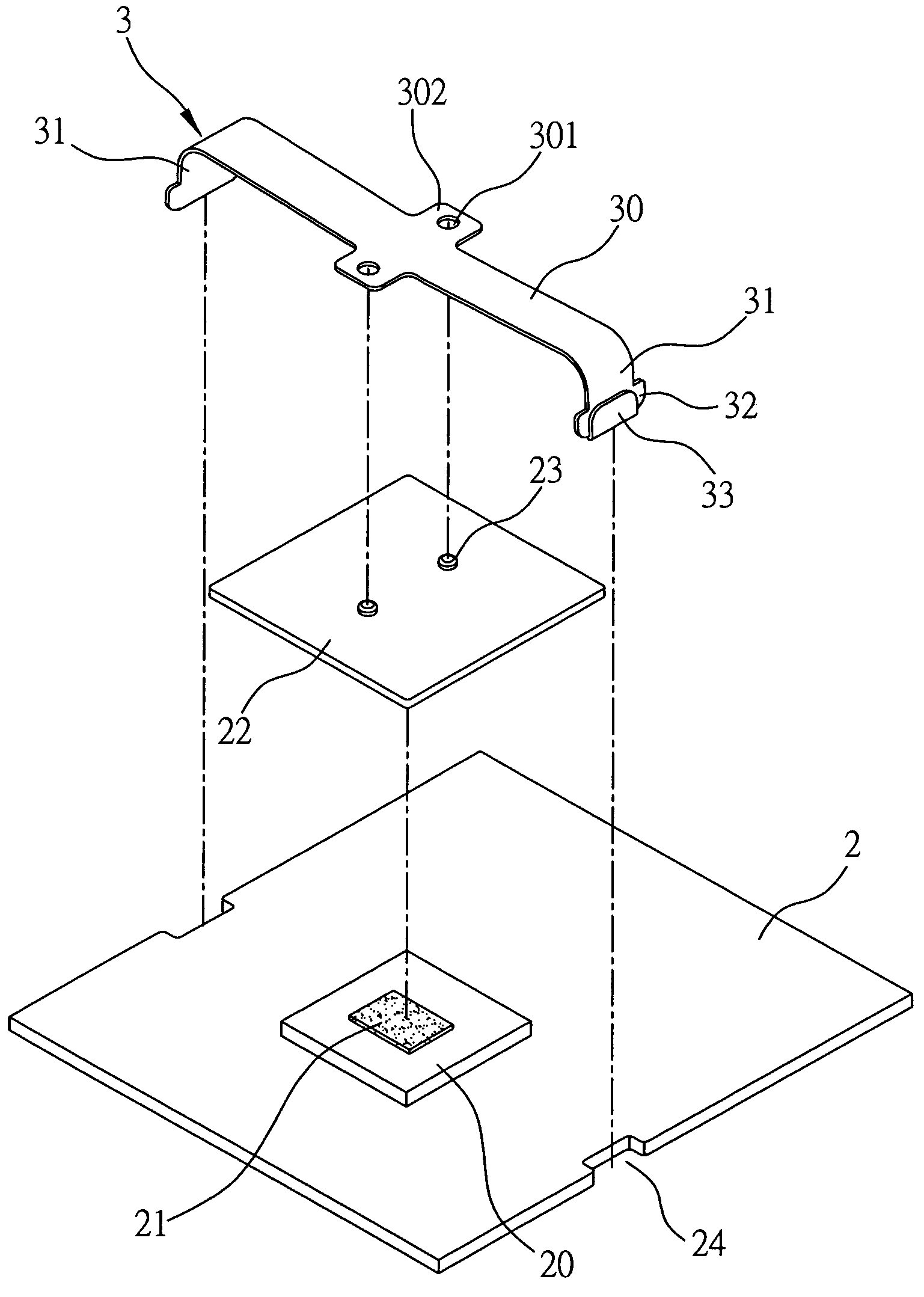
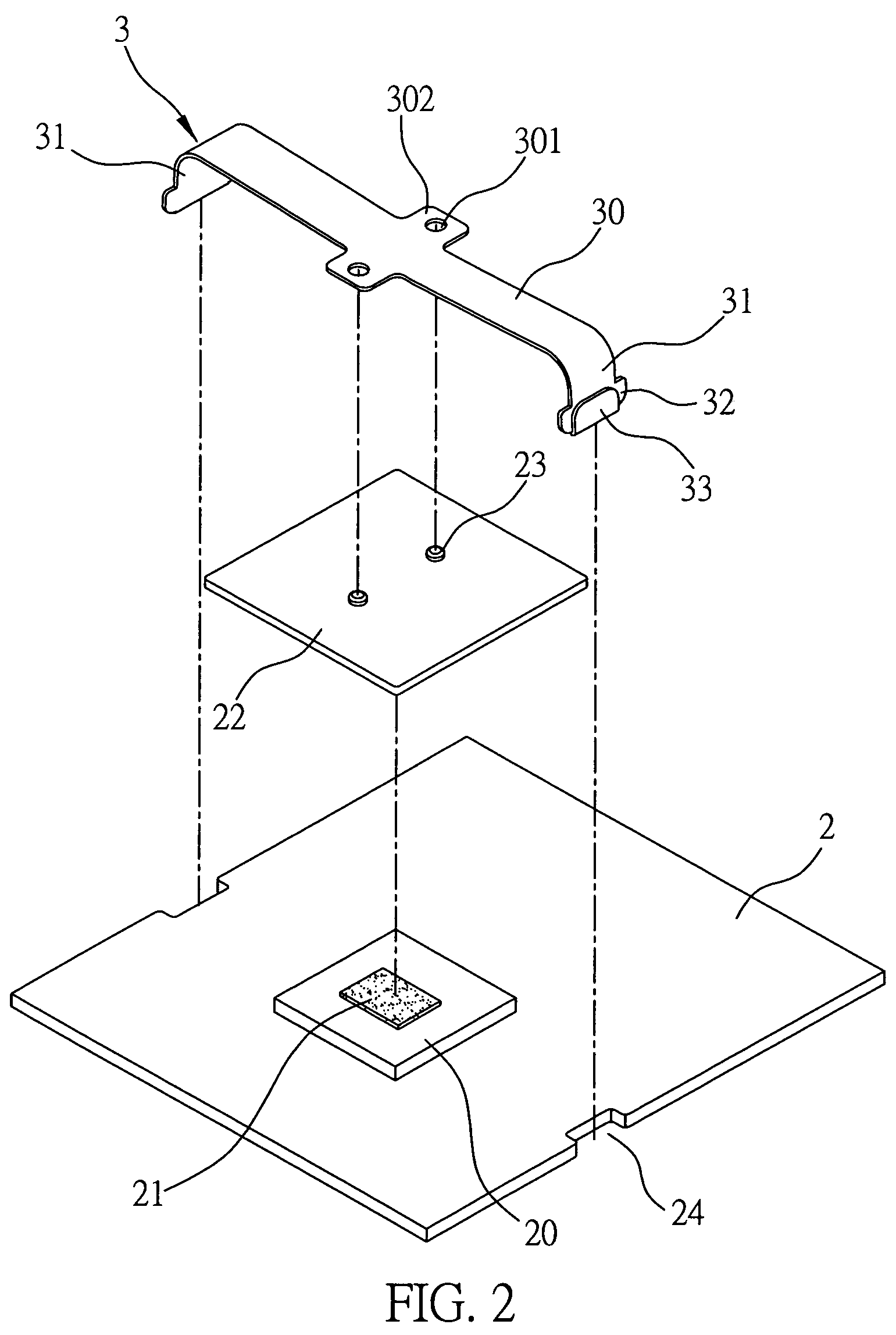
[0019]Referring to FIG. 2, which is an exploded view showing how to fasten a heat sink 22 to an electronic device 20 mounted on a circuit board 2 with a fastening mechanism 3 of the present invention. The heat sink 22 comprises a first positioning portion 23. Two opposite sides of the circuit board 2 are disposed with a notch 24 each. The electronic device 20 is, for example, a semiconductor chip coated with thermally conductive adhesive 21 for transferring to the heat sink 22 any heat generated by the electronic device 20 with a view to speeding up heat dissipation. The fastening mechanism 3 comprises a body 30, at least two bending portions 31, and at least two snap-fit portions 32. The body 30 presses on the heat sin...


PUM


Abstract

The present invention discloses a fastening mechanism for fastening a heat sink to the surface of an electronic device mounted on a circuit board, the heat sink being provided with a first positioning portion, the circuit board having two opposite sides each formed with a notch. The fastening mechanism at least includes a body for pressing the heat sink on the electronic device, at least two bending portions corresponding in position to and striding over the notches respectively, and at least two snap-fit portions disposed at the end of each of the bending portions and wider than the notches respectively, to enable snap-fit engagement of the snap-fit portions with the edges of the notches of the circuit board, thereby effectively fastening the heat sink to the electronic device.

Description

BACKGROUND OF THE INVENTION[0001]1. Field of the Invention[0002]The present invention relates to a fastening mechanism, and more particularly, to a fastening mechanism for fastening a heat sink to an electronic device.[0003]2. Description of the Prior Art[0004]With continual advances in electronic technology, the computation function of a computer is becoming more powerful, and computation by a new generation chip is faster than it has ever been before. As a result, chips in operation generate an increasing amount of heat. To prevent heat generated by a chip in operation from damaging the chip or shortening the life of the chip, a heat sink is disposed on the chip as disclosed in the prior art, to transfer any heat generated by the chip in operation to the heat sink, and cool air is driven to the heat sink by fan to speed up heat dissipation.[0005]However, a conventional heat sink is typically fastened to a chip by means of thermally conductive tape or adhesive, though inefficiently...

Claims


Application Information

Patent Timeline
IPC IPC(8): H05K7/20
CPCH01L23/4093H01L2924/0002H01L2924/00
Inventor CHANG, LIN-WEI
Owner INVENTEC CORP
Why Eureka
Try Eureka