Optical recording method on multilayer optical recording medium, optical recording apparatus, and multilayer optical recording medium

a multi-layer optical recording medium and optical recording technology, applied in the detection/correction of digital signals, instruments, recording signals, etc., can solve problems such as recording errors, recording errors, recording errors, etc., and achieve the effect of limiting any reduction in recording rate and storage capacity

Inactive Publication Date: 2008-06-05
TDK CORPARATION
View PDF4 Cites 10 Cited by
  • Summary
  • Abstract
  • Description
  • Claims
  • Application Information

AI Technical Summary

Benefits of technology

[0023]According to the information recording method and the like of the present invention, when a defect area is detected in a recording layer of a multilayer opti

Problems solved by technology

When information is recorded by irradiating a recording layer of an optical recording medium with a beam spot of a laser or the like, various factors can cause a recording error.
Some of the factors that can cause a recording error include the meandering of a recording track on the optical recording medium, bumps and dips in the recording track, air bubbles in a spacer layer, and the like.
Other factors causing a recording error may also include foreign matter such as a fingerprint, dust, and the like adhering to the surface of the optical recording medium.
Thus, when the innermost or outermost circumference is scratched, all the defect management areas become unavailable at the same time.
Thus, in the case of a recording method in which the number of revolutions of a motor varies in accordance with the radial position of the optical pickup, like zone CLV, there is a problem in that control over the number of revolutions of the optical recording medium takes time and hence the recording rate is reduced during the escape operation.
As a result of this, there

Method used


Image

  • Optical recording method on multilayer optical recording medium, optical recording apparatus, and multilayer optical recording medium
  • Optical recording method on multilayer optical recording medium, optical recording apparatus, and multilayer optical recording medium
  • Optical recording method on multilayer optical recording medium, optical recording apparatus, and multilayer optical recording medium

Examples


Embodiment Construction

[0030]Embodiments of the present invention will be described in detail with reference to the accompanying drawings.

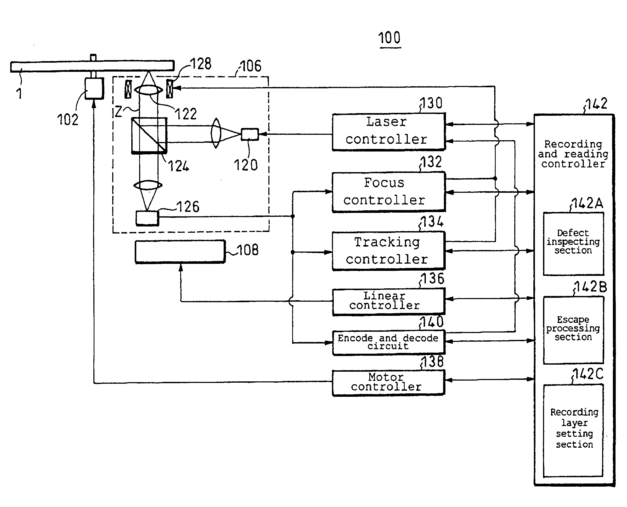
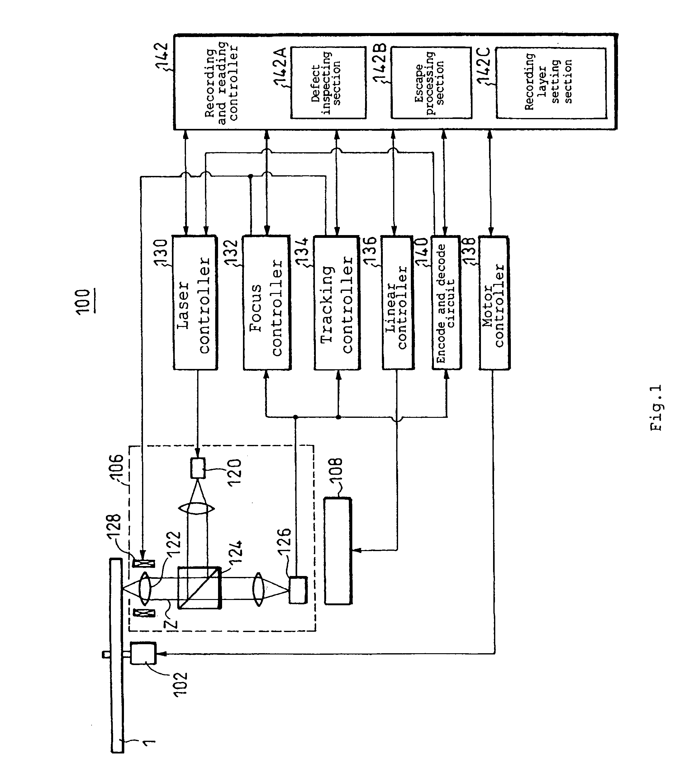
[0031]FIG. 1 shows a recording and reproducing apparatus 100 which illustrates an optical recording method according to various embodiments of the present invention. The recording and reproducing apparatus 100 is provided with a motor 102, an optical pickup 106, and a linear drive mechanism 108. The motor 102 rotates an optical recording medium 1. The optical pickup 106 irradiates the optical recording medium 1 with a beam spot to record and reproduce information. The linear drive mechanism 108 linearly drives the optical pickup 106 in a radial direction of the optical recording medium 1. The optical recording medium 1 is a multilayer optical recording medium which has a plurality of recording layers for recording information on.

[0032]The optical pickup 106 is provided with a laser light source 120, an objective lens 122, a half mirror 124, a photo-detection device 126,...


PUM


Abstract

When there is a defect area in a specific recording layer, recording of information is continued and reduction in a recording rate is restrained. In an optical recording method for recording information on a multilayer optical recording medium having a plurality of recording layers by irradiating the recording layer with a beam spot, any recording layer is set as an escape recording layer. When a defect area is detected while information is recorded on another recording layer except for the escape recording layer, the beam spot moves to the escape recording layer to continue recording the information.

Description

BACKGROUND OF THE INVENTION[0001]1. Field of the Invention[0002]The present invention relates to an optical recording method on a multilayer optical recording medium having a plurality of recording layers, an optical recording apparatus adopting the recording method, and a multilayer optical recording medium.[0003]2. Description of the Related Art[0004]When information is recorded by irradiating a recording layer of an optical recording medium with a beam spot of a laser or the like, various factors can cause a recording error. Some of the factors that can cause a recording error include the meandering of a recording track on the optical recording medium, bumps and dips in the recording track, air bubbles in a spacer layer, and the like. Other factors causing a recording error may also include foreign matter such as a fingerprint, dust, and the like adhering to the surface of the optical recording medium.[0005]In order to appropriately avoid a defect area in which any such factor ex...

Claims


Application Information

Patent Timeline
IPC IPC(8): G11B20/18G11B7/00G11B7/24038
CPCG11B2220/215G11B2220/235G11B2220/2537G11B7/0045G11B2220/20G11B7/24038G11B7/24085G11B20/1883G11B2007/0013G11B7/007
Inventor KIKUKAWA, TAKASHIMISHIMA, KOJIAOYAMA, TSUTOMUITOH, HIDETAKE
Owner TDK CORPARATION
Why Eureka
Try Eureka