Image forming apparatus and image forming apparatus control method

Inactive Publication Date: 2008-06-05
CANON KK
View PDF4 Cites 22 Cited by
  • Summary
  • Abstract
  • Description
  • Claims
  • Application Information

AI Technical Summary

Benefits of technology

[0037]The present invention can maintain the throughput, and maintain

Problems solved by technology

According to this proposal, however, it is difficult to cope with a case where the state of the image forming apparatus deviates from the image forming condition table due to an unexpected use.
With this proposal, however, it is difficult to satisfy both the control frequency and maintenance of the throughput.
However, the maximum density cannot be adjusted to a desired one.
For example, even if the maximum density decreases upon the lapse of ti

Method used


Image

  • Image forming apparatus and image forming apparatus control method
  • Image forming apparatus and image forming apparatus control method
  • Image forming apparatus and image forming apparatus control method

Examples


Example

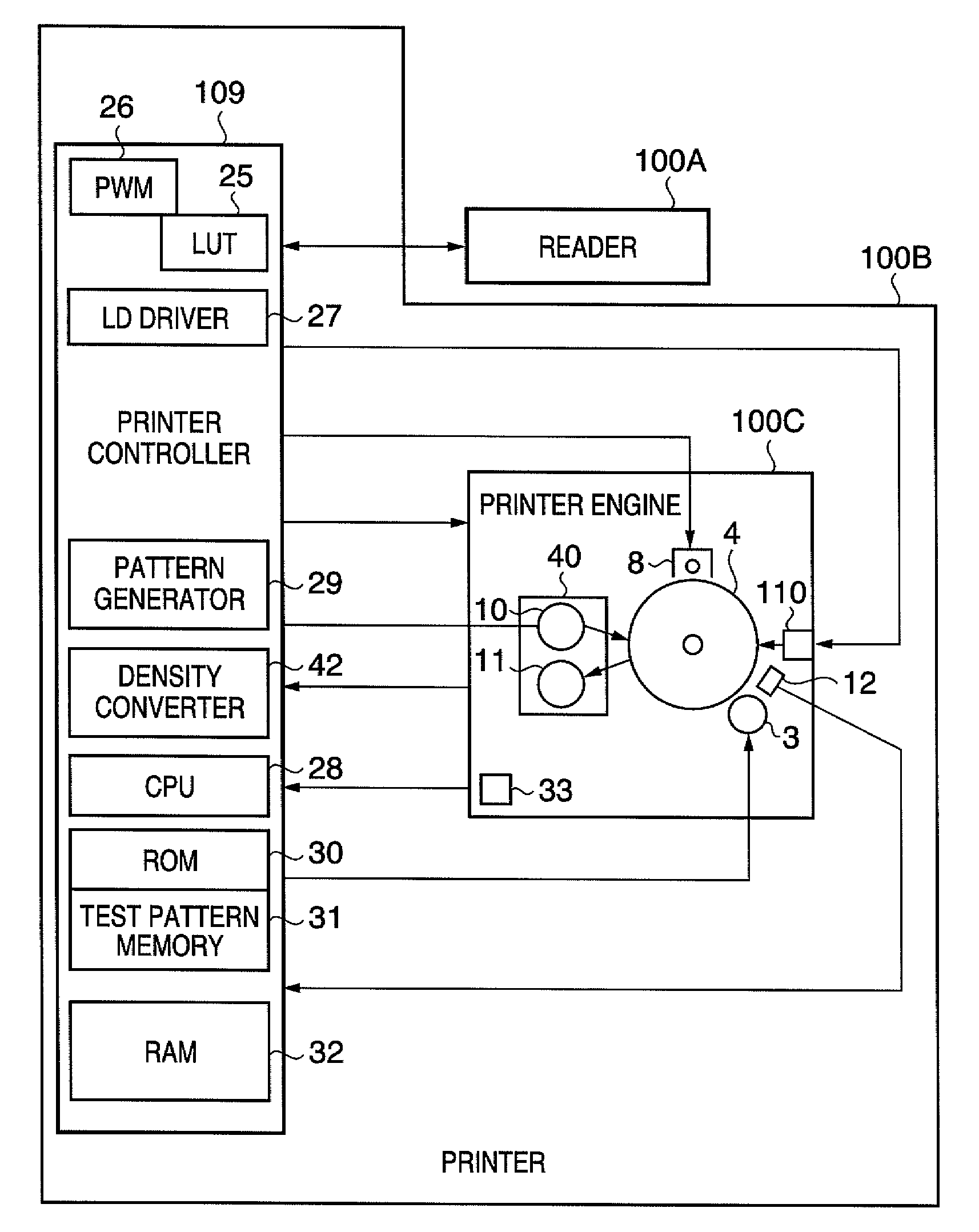
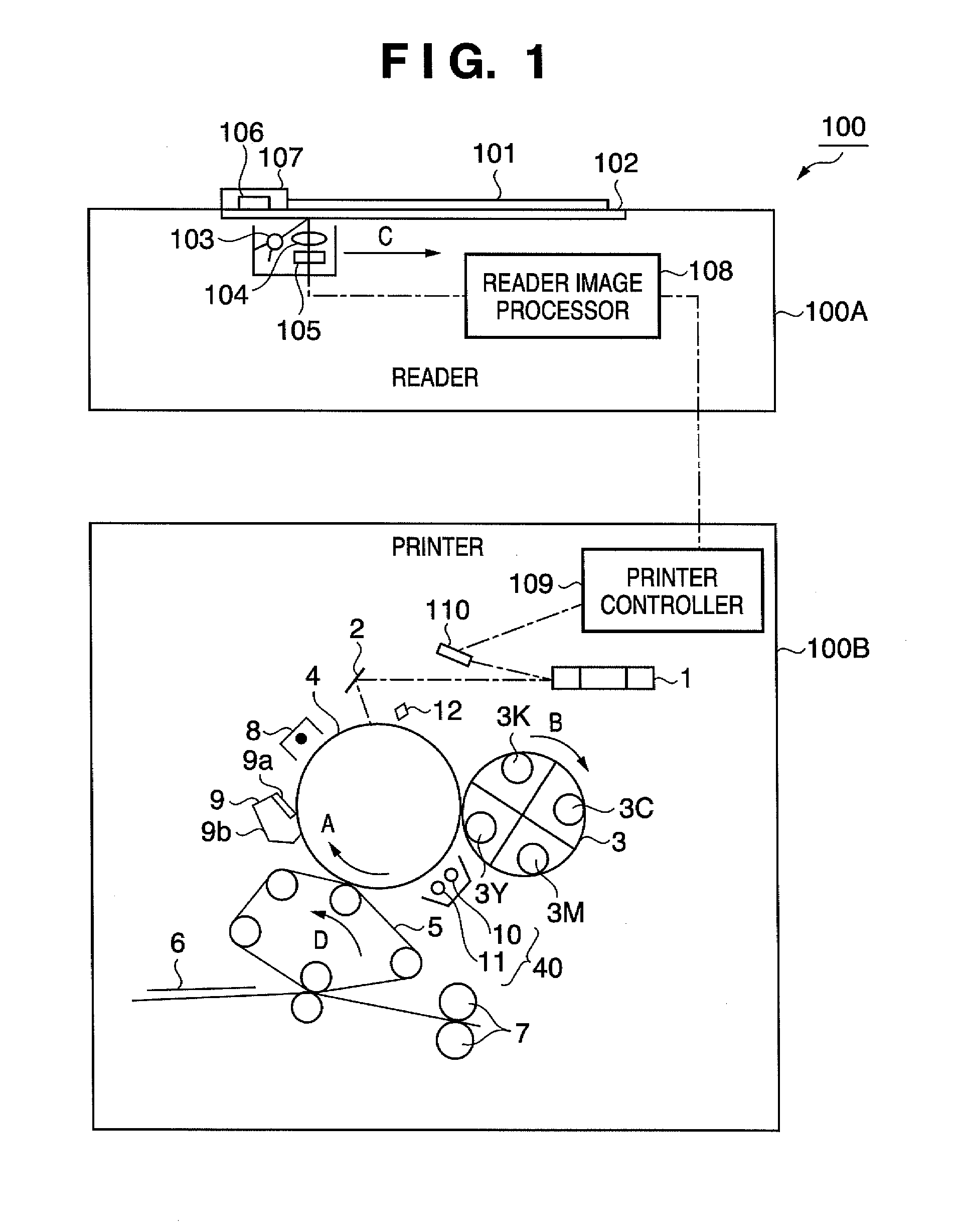
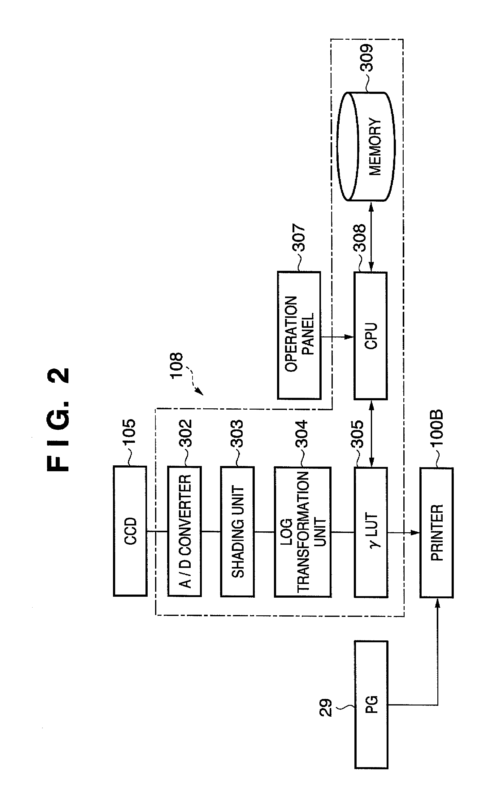
[0057]An embodiment of the present invention will be described below with reference to the accompanying drawings. FIG. 1 is a schematic sectional view for explaining an image forming apparatus as an example of the embodiment of the present invention. FIG. 2 is a control block diagram for explaining the image processor of a reader. FIG. 3 is a control block diagram of the image forming apparatus as an example of the embodiment of the present invention.

[0058]As shown in FIG. 1, an image forming apparatus 100 as an example of the embodiment of the present invention comprises a reader (image reading device) 100A and printer 100B.

[0059]The reader 100A will be described first.

[0060]The reader 100A comprises an original plate 102. An original 101 set on the original plate 102 is irradiated by a light source 103, and light reflected by the original 101 is formed into an image on a CCD sensor 105 via an optical system 104.

[0061]In the CCD sensor 105, three arrays of red, green, and blue CCD ...


PUM


Abstract

In an image forming apparatus, an image forming contrast potential for obtaining the maximum density is set by reading a specific pattern transferred and formed on a sheet. A photosensor detects the density of a specific pattern formed on an image carrier at the image forming contrast potential, and the detection result is stored. A correction amount for the image forming contrast potential is calculated on the basis of the relationship between the stored detected density, and the density, detected by the optical sensor, of the specific pattern formed on the image carrier at a predetermined timing. The image forming contrast potential is adjusted by the correction amount.

Description

BACKGROUND OF THE INVENTION[0001]1. Field of the Invention[0002]The present invention relates to an image forming apparatus such as a copying machine or laser beam printer which forms an image by transferring a toner image of at least one color onto a sheet by an electrophotographic method or electrostatic recording scheme, and an image forming apparatus control method.[0003]2. Description of the Related Art[0004]FIG. 18 shows an example of a conventional image forming apparatus.[0005]The image forming apparatus comprises a rotary developing unit 3 rotatably supported by a rotation support (not shown). The rotary developing unit 3 includes a yellow toner developing unit 3Y, magenta toner developing unit 3M, cyan toner developing unit 3C, and black toner developing unit 3K.[0006]The color toner developing units 3Y, 3M, 3C, and 3K of the rotary developing unit 3 sequentially face a photosensitive drum 4 to develop images with the respective color toners.[0007]The photosensitive drum 4...

Claims


Application Information

Patent Timeline
IPC IPC(8): G03G15/00
CPCG03G15/5062G03G15/5041G03G2215/00042
Inventor KOMIYA, YOSHIYUKI
Owner CANON KK
Why Eureka
Try Eureka