Systems and methods for electrical storage device isolation

a technology of electrical storage device and isolation system, which is applied in the direction of primary cell maintenance/service, paper/cardboard containers, cell components, etc., can solve the problems of inability to easily estimate the remaining life of a battery, difficulty in carrying additional batteries, etc., and achieves the effect of efficiently containing a used/expended electrical storage device without risking exposure to toxic chemicals or long-term environmental damag

Active Publication Date: 2008-06-05
KENNEDY DOUG +1
View PDF16 Cites 7 Cited by
  • Summary
  • Abstract
  • Description
  • Claims
  • Application Information

AI Technical Summary

Benefits of technology

[0007]Embodiments of the present invention represent a significant advance in electrical device isolation and storage. The ability to electrically isolate a discharged battery in a mobile environment enables proper disposal and minimizes risks of toxic chemical leakage and/or exposure. A user may therefore efficiently contain a used/expended electrical storage devic...

Problems solved by technology

One of the problems with long-term portable electric device usage is the necessity to carry additional batteries.
Since a user cannot easily estimate the remaining life of a battery or the battery usage required for a particular activity, it is generally necessary to carry extra batteries.
Carrying additional batteries is problematic for many reasons, including inadvertent loss, inconvenience, battery damage, or improperly sized additional batteries.
Another problem associated with carrying ex...

Method used


Image

  • Systems and methods for electrical storage device isolation
  • Systems and methods for electrical storage device isolation
  • Systems and methods for electrical storage device isolation

Examples


second embodiment

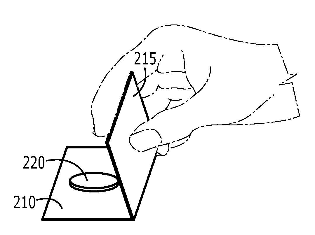
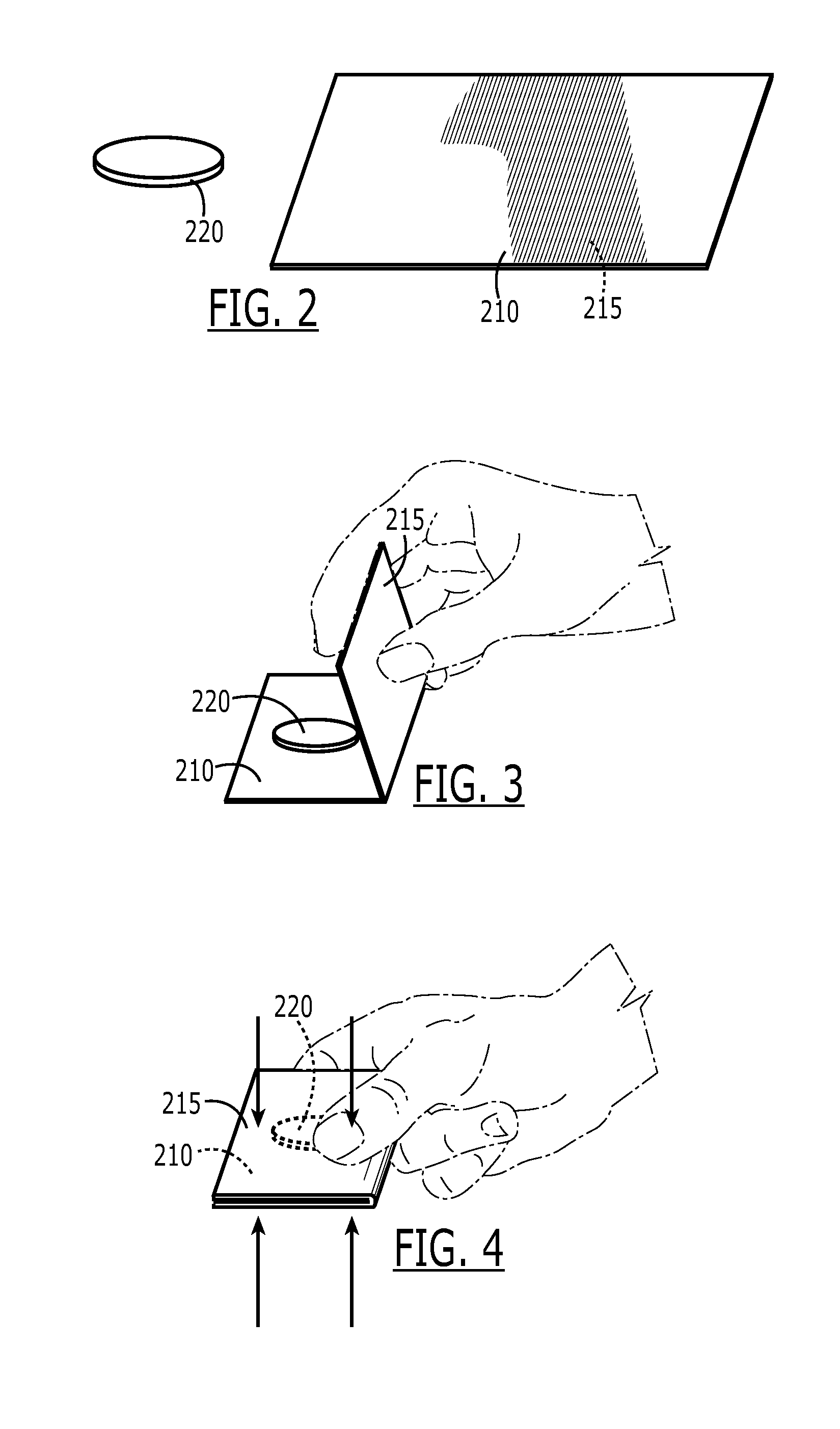
[0027]Reference is next made to FIGS. 2-4, which illustrate a method of electrically isolating a battery in accordance with the present invention. The method of electrical isolation includes providing an electrical storage device, such as the illustrated coin cell battery 220, and an adhesive member, such as a substantially two dimensional member with an adhesive side 210 and a non-adhesive side 215. As described above, the adhesive side 210 may include some form of adhesive agent to generate a repeatable adhesion. It will be appreciated that the adhesive side 210 may include one or more adhesive regions that do not necessarily extend across the entire two dimensional surface of the adhesive side. For example, an adhesive region may include a non-adhesive gap corresponding to the battery 220 and / or the location at which the folding occurs (not shown). A surface of the battery 220 is coupled to a first portion of the adhesive side 210 within the two dimensional area of the adhesive s...

third embodiment

[0028]Reference is next made to FIGS. 5-7, which illustrate a method of electrically isolating a battery in accordance with the present invention. The method of electrical isolation includes providing an electrical storage device, such as the illustrated coin cell battery 320, and two adhesive members, such as the first and second members with adhesive sides 310, 330 and non-adhesive sides 315, 335. As described above, the adhesive sides 310, 330 may include some form of adhesive agent to generate a repeatable adhesion. It will be appreciated that the adhesive sides 310, 330 may include one or more adhesive regions that do not necessarily extend across the entire two dimensional surface of the adhesive side. For example, an adhesive region may include a non-adhesive gap corresponding to the battery 320. A surface of the battery 320 is coupled to a portion within the two dimensional area of the first adhesive side 310, as illustrated. The coupling may be achieved by either adhesion o...


PUM

PropertyMeasurementUnit
Forceaaaaaaaaaa
Volumeaaaaaaaaaa
Adhesion strengthaaaaaaaaaa

Abstract

The present invention relates to adhesive-based battery isolation systems and methods of use. Embodiments of the present invention include utilizing one or more adhesive members to electrically isolate a used battery or electrical storage device such that it may be positioned back within an open package for storage without exposure to moisture. One embodiment of the present invention relates to an electrical storage and isolation system including an electrical storage device, a storage compartment, and at least one adhesive member. The storage compartment may be any form of storage compartment with a releasable opening such as conventional retail plastic package or a flexible retort type package. The system may include one or more adhesive members for use in electrically isolating an electrical storage device.

Description

RELATED APPLICATIONS[0001]This application claims priority to U.S. provisional application Ser. No. 60 / 868,383 filed Dec. 4, 2006, the contents of which are incorporated by reference.FIELD OF THE INVENTION[0002]The invention generally relates to electrical storage systems such as batteries. In particular, the present invention relates to an adhesive-based battery isolation system and method of use.BACKGROUND OF THE INVENTION[0003]Portable electrical devices require a power source or power supply to provide the necessary electricity to operate. For example, flashlights commonly utilize one or more batteries to provide electricity to illuminate an LED or bulb. A battery is a common type of portable electric power source. Batteries are designed to provide a particular amperage and voltage for a particular duration or capacity. The size of a battery is directly proportional to the voltage, amperage, and capacity. Batteries are made with various form factors, output voltages, output ampe...

Claims


Application Information

Patent Timeline
IPC IPC(8): H01M2/04B32B37/00
CPCB65D75/20B65D75/30B65D2585/88Y10T156/10H01M2/1094H01M6/5072H01M2/1011H01M50/24H01M50/256
Inventor KENNEDY, DOUGKENNEDY, GREG
Owner KENNEDY DOUG
Why Eureka
Try Eureka