Inflatable artificial valve

a technology of artificial valves and valves, which is applied in the field of artificial valves, can solve problems such as limiting the use of artificial valves

Inactive Publication Date: 2008-06-05
GELBART DANIEL +1
View PDF6 Cites 41 Cited by
  • Summary
  • Abstract
  • Description
  • Claims
  • Application Information

AI Technical Summary

Benefits of technology

[0003]According to the invention, the artificial valve is delivered percutaneously in the form of a hollow inflatable shell, which is later filled in situ with a suitable elastomer, similar to inflating a balloon. Since the shell is a flexible and mostly hollow balloon, it can be compressed and transported via a relatively small catheter. In order to inflate to the correct shape the hollow shell requir...

Problems solved by technology

This greatly limits the use of such valves as the hole ...

Method used


Image

  • Inflatable artificial valve
  • Inflatable artificial valve
  • Inflatable artificial valve

Examples


Embodiment Construction

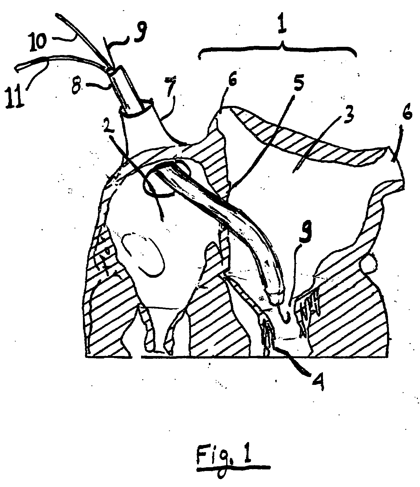
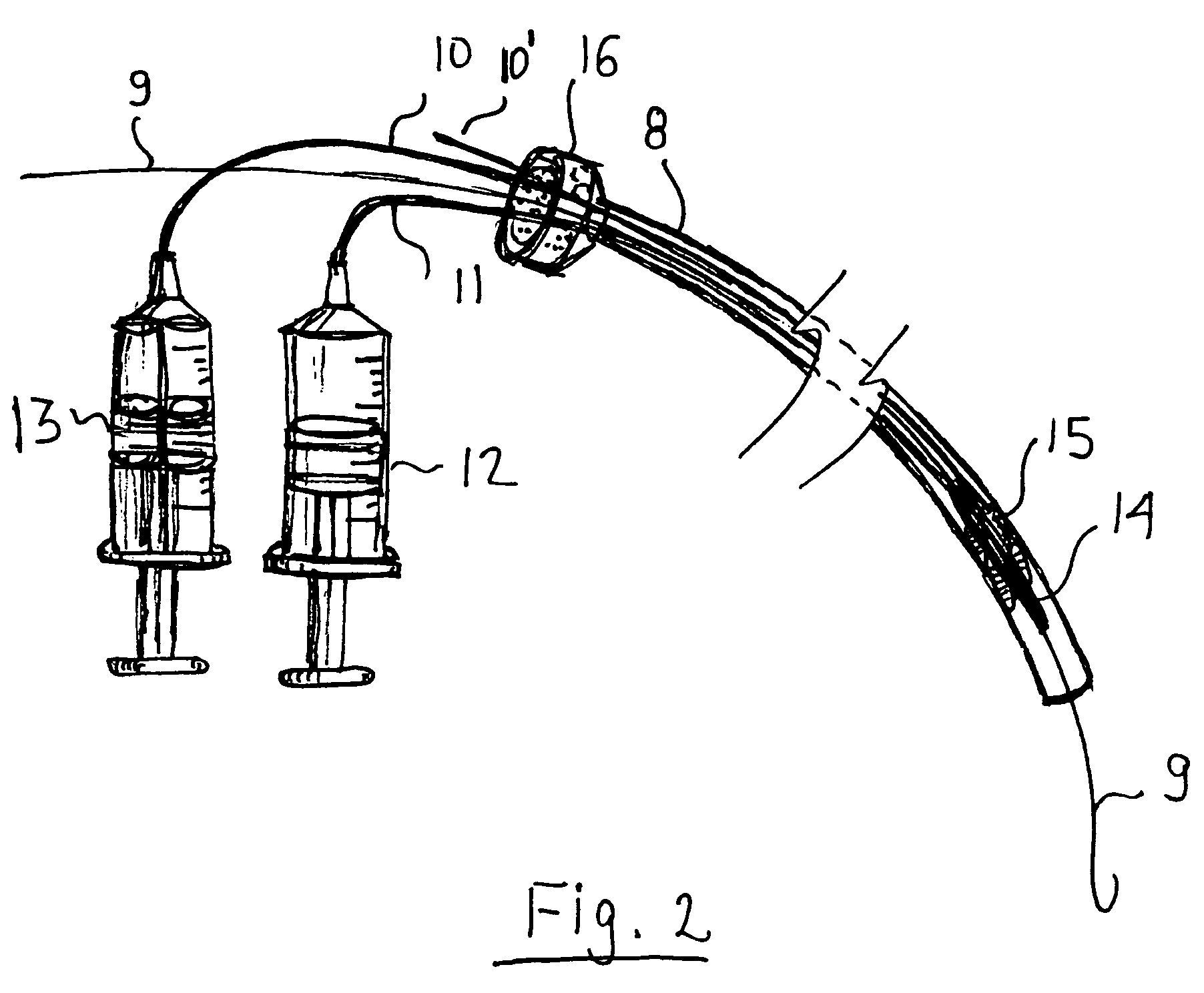
[0016]While the invention is suitable for many different artificial valves in the human body, the example given in the preferred embodiment will be a mitral valve replacement. FIG. 1 is a partial cross section of a human heart 1, comprising of a right atrium 2, left atrium 3, mitral valve 4, septum 5, pulmonary veins 6 and superior vena cava 7. A catheter 8 is introduced percutaneously via the superior vena cava 7 into the left atrium 3 via the septum 5. Normally a guide wire 9 is introduced first, followed by a catheter having a dilator (not shown). After catheter 8 is in place, the valve is introduced. The valve is connected to the outside of the body by two inflation tubes, 10 and 11 (details of the valve insertion are given later). In this example the catheter is positioned near the mitral valve. The procedure of percutaneously delivery is well known to those skilled in the art of interventional cardiology or catheter based surgical procedures. It is similar to the well known pr...


PUM


Abstract

An artificial valve is delivered percutaneously in the form of a hollow inflatable shell, which is later filled in situ with a suitable elastomer, similar to inflating a balloon. Since the shell is a flexible and mostly hollow balloon, it can be compressed and transported via a relatively small catheter. In order to inflate to the correct shape the hollow shell requires some ties between its walls. These ties are formed from a low density open cell foam or a specialized manufacturing process. The valve can combine elements with different stiffness as well as different materials. A positioning balloon can also be used in the process of placing the valve. The invention is particularly suited for cardiac valves but can be used for other artificial valves.

Description

FIELD OF INVENTION [0001]The invention relates to artificial valves installed in the body percutaneously, and in particular to cardiac valves.BACKGROUND OF THE INVENTION [0002]Artificial valves, and in particular artificial cardiac valves, have been used for a long time. Recently the trend is to install them percutaneously, via a catheter. Current catheters capable of delivering today's valve are fairly large (size 24Fr and sometimes larger). This greatly limits the use of such valves as the hole left in the vascular system or the heart wall is significant. An object of the invention is to deliver a large size valve, such as a cardiac valve, via a very small catheter without damaging the valve in the process. A second object is to have a valve than can be anchored in an irregular area, such as to replace a faulty mitral valve. A third object is to seat the valve forming a hemostatic seal without any high local pressures that can cause calcified deposits to break off, such as in an a...

Claims


Application Information

Patent Timeline
IPC IPC(8): A61F2/24A61F2/02
CPCA61F2/2412A61F2/2415A61L27/507A61F2250/0003A61L27/50A61F2/2427
Inventor GELBART, DANIELLICHTENSTEIN, SAMUEL VICTOR
Owner GELBART DANIEL
Why Eureka
Try Eureka