Audio Coding Based on Block Grouping

a technology of audio coding and block grouping, applied in the field of audio coding based on block grouping, can solve the problems of severe data limit, limited bandwidth or space that is available for transmitting or recording encoded signals, and further reduce the amount of data that may be used to represent quantized signals. , to achieve the effect of optimizing signal processing performan

Inactive Publication Date: 2008-06-05
KONINKLIJKE PHILIPS ELECTRONICS NV +1
View PDF10 Cites 12 Cited by
  • Summary
  • Abstract
  • Description
  • Claims
  • Application Information

AI Technical Summary

Benefits of technology

[0008]In accordance with the present invention, blocks of audio information arranged in frames are grouped into one or more sets or groups of blocks such that every block is in a respective group. Each group may consist of a single block or a set of two or more blocks within a frame and a process that is applied to each block in the group uses a common set of one or more control parameters such as, for example, a set of scale factors. The present invention is directed toward controlling the grouping of blocks to optimize signal processing performance.

Problems solved by technology

In many coding applications, the bandwidth or space that is available to transmit or record an encoded signal is limited and this limitation imposes severe constraints on the amount of data that may be used to represent the quantized spectral components.
Data needed to convey sets of control parameters are an overhead that further reduces the amount of data that may be used to represent the quantized spectral components.
Unfortunately, audio signals are not stationery and the efficiency of the encoding process for all blocks of audio information in a frame may not be optimum if the control parameters are shared by too many blocks.

Method used


Image

  • Audio Coding Based on Block Grouping
  • Audio Coding Based on Block Grouping
  • Audio Coding Based on Block Grouping

Examples


Embodiment Construction

A. Introduction

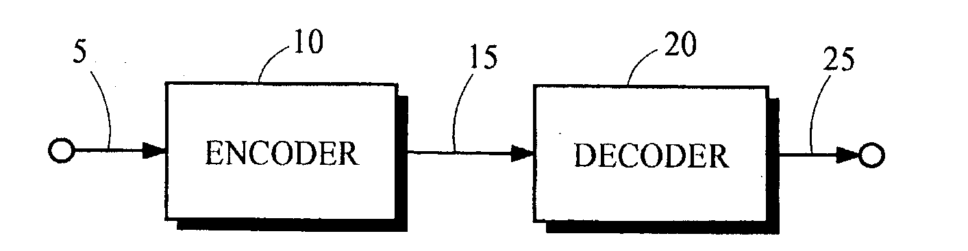
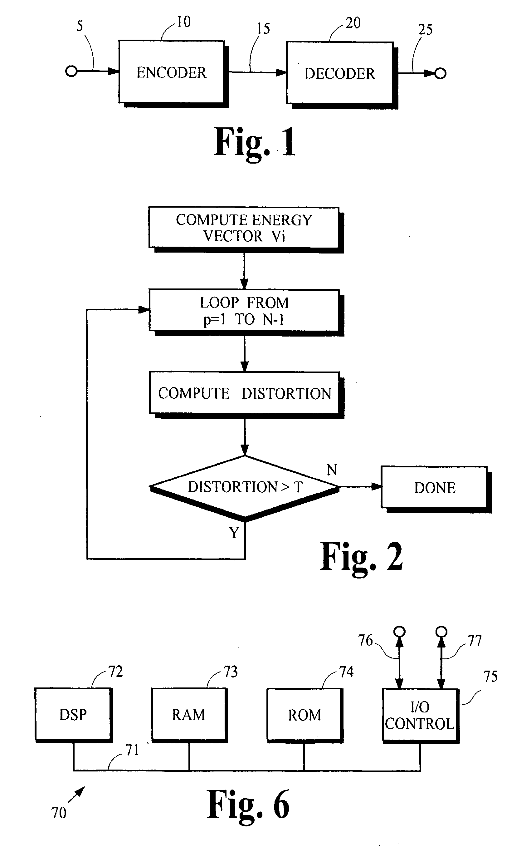
[0017]FIG. 1 illustrates an audio coding system in which an encoder 10 receives from the path 5 one or more streams of audio information representing one or more channels of audio signals. The encoder 10 processes the streams of audio information to generate along the path 15 an encoded signal that may be transmitted or recorded. The encoded signal is subsequently received by the decoder 20, which processes the encoded signal to generate along the path 25 a replica of the audio information received from the path 5. The content of the replica may not be identical to the original audio information. If the encoder 10 uses a lossless encoding method to generate the encoded signal, the decoder 20 can in principle recover a replica that is identical to the original audio information streams. If the encoder 10 uses a lossy encoding technique such as perceptual coding, the content of the recovered replica generally is not identical to the content of the original stream but it...


PUM


Abstract

Blocks of audio information are arranged in groups that share encoding control parameters to reduce the amount of side information needed to convey the control parameters in an encoded signal. The configuration of groups that reduces the distortion of the encoded audio information may be determined by any of several techniques that search for an optimal or near optimal solution. The techniques include an exhaustive search, a fast optimal search and a greed merge, which allow the search technique to tradeoff the reduction in distortion against the bit rate of the encoded signal and/or the computational complexity of the search technique.

Description

TECHNICAL FIELD[0001]The present invention relates to optimizing the operation of digital audio encoders of the type that apply an encoding process to one or more streams of audio information representing one or more channels of audio that are segmented into frames, each frame comprising one or more blocks of digital audio information. More particularly, the present invention relates to grouping blocks of audio information arranged in frames in such a way as to optimize a coding process that is applied to the frames.BACKGROUND ART[0002]Many audio processing systems operate by dividing streams of audio information into frames and further dividing the frames into blocks of sequential data representing a portion of the audio information in a particular time interval. Some type of signal processing is applied to each block in the stream. Two examples of audio processing systems that apply a perceptual encoding process to each block are systems that conform to the Advanced Audio Coder (A...

Claims


Application Information

Patent Timeline
Patent Type & Authority Applications(United States)
IPC IPC(8): G10L19/00G10L19/02
CPCG10L19/032G10L19/02G10L25/60
Inventor FELLERS, MATTHEW CONRADVINTON, MARK STUARTBAUER, CLAUS
Owner KONINKLIJKE PHILIPS ELECTRONICS NV
Why Eureka
Try Eureka