Configuration Management for Co-Located Network Systems

Inactive Publication Date: 2008-06-05
THOMSON LICENSING SA
View PDF2 Cites 53 Cited by
  • Summary
  • Abstract
  • Description
  • Claims
  • Application Information

AI Technical Summary

Problems solved by technology

This unfortunately permits an STB to be moved to another location outside of the original video distribution system.
A problem arises when a subscriber giv

Method used


Image

  • Configuration Management for Co-Located Network Systems
  • Configuration Management for Co-Located Network Systems
  • Configuration Management for Co-Located Network Systems

Examples


Embodiment Construction

[0015]It is to be understood that the figures and descriptions of the present invention have been simplified to illustrate elements that are relevant for a clear understanding of the present invention, while eliminating, for purposes of clarity, many other elements found in typical content distribution systems and methods. Those of ordinary skill in the art will recognize that other elements are desirable and / or required in order to implement the present invention. However, because such elements are well known in the art, and because they do not facilitate a better understanding of the present invention, a discussion of such elements is not provided herein. Further, the embodiments disclosed herein are not intended to be exhaustive or limit the invention to the precise form disclosed so that others skilled in the art may utilize its teaching.

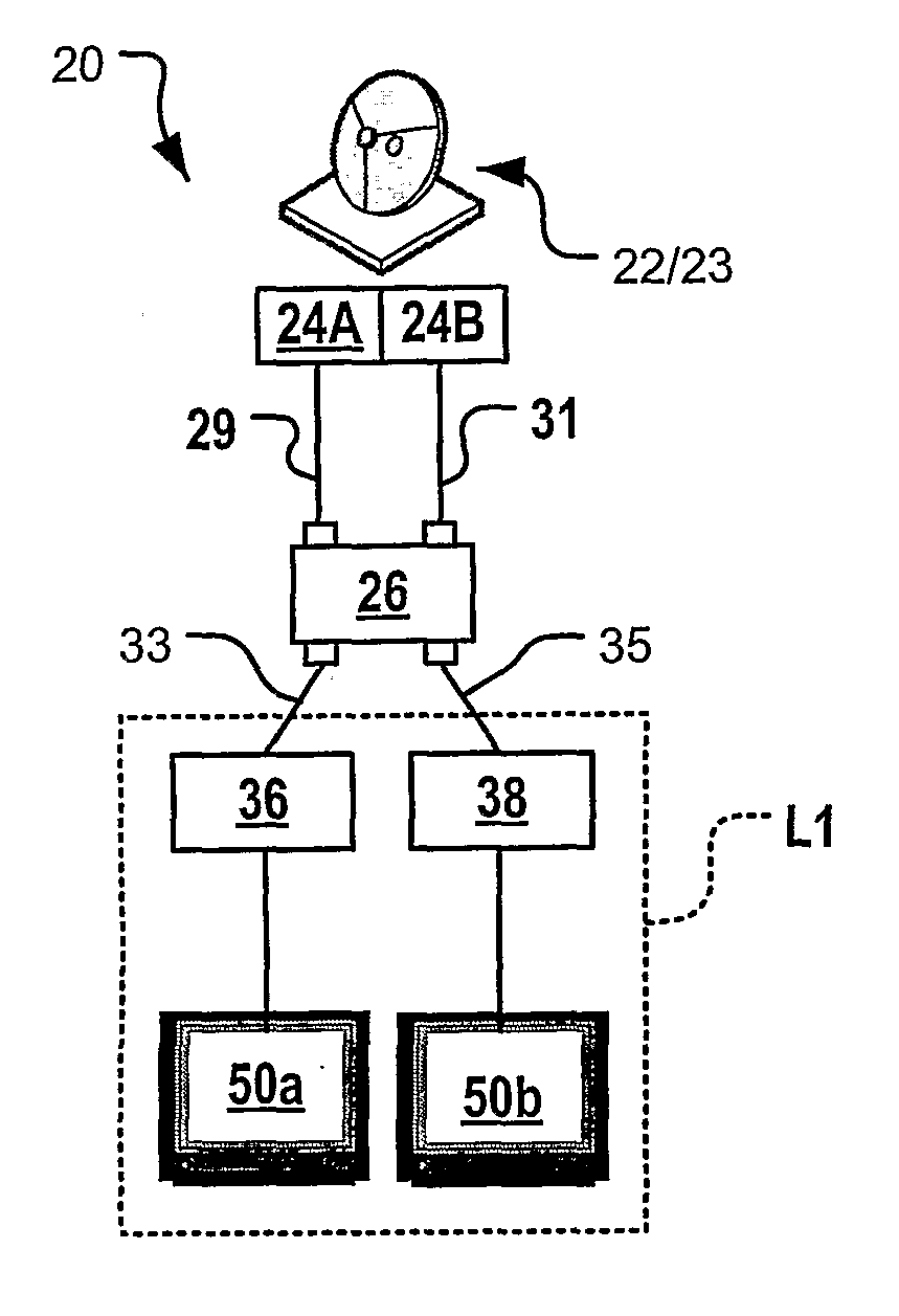
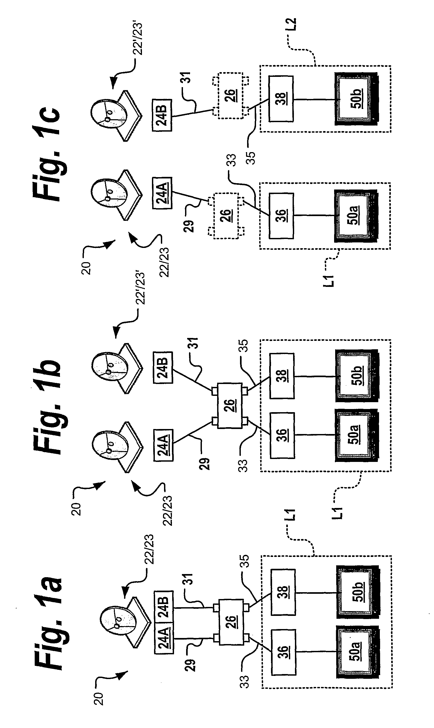
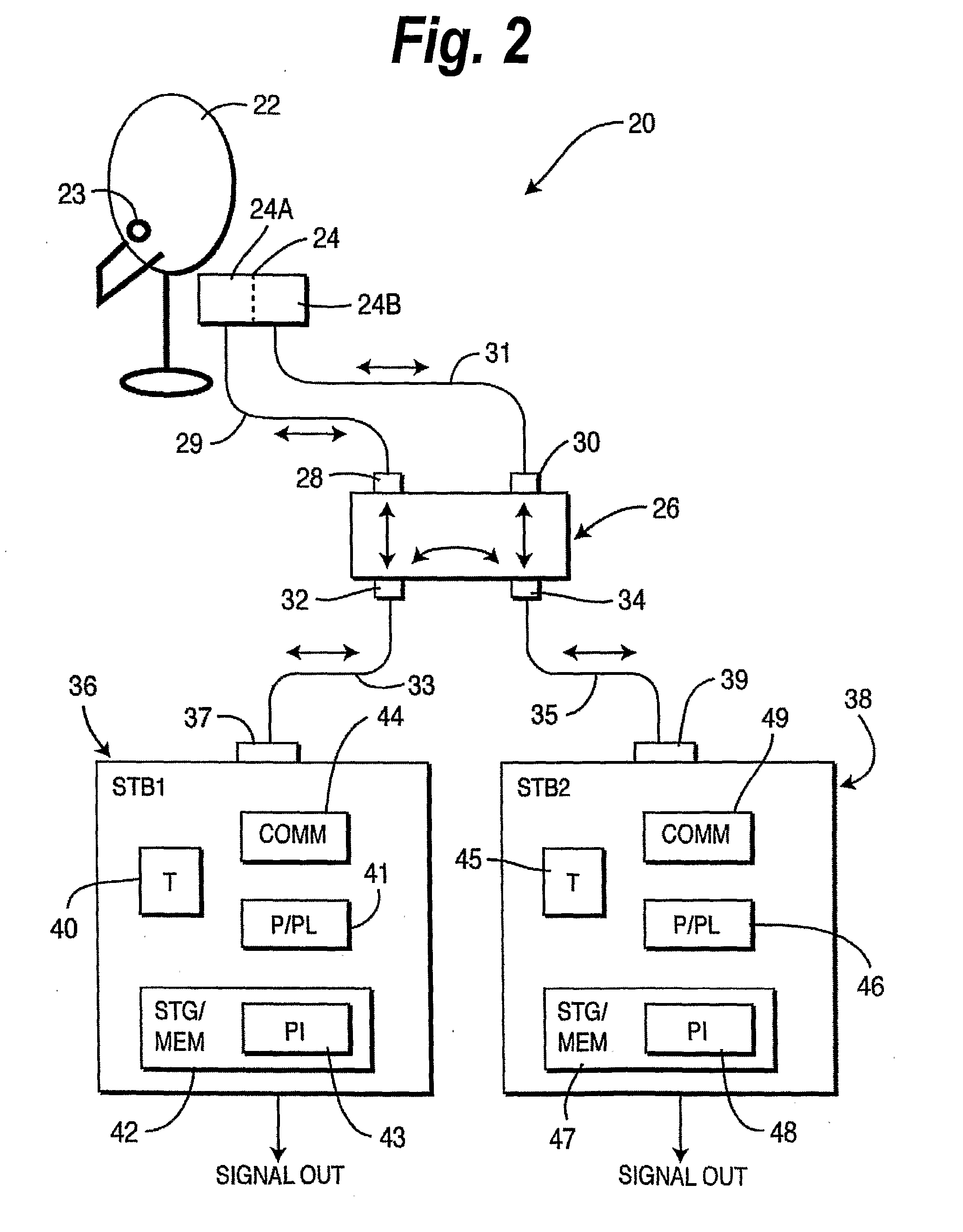
[0016]According to an aspect of the present invention, a method and system for connecting multiple set top boxes (STBs) to receive service prov...


PUM


Abstract

One receiver is configured in the main state and the other receivers are configured in the secondary state. The receivers are communicatively coupled to each other via a local communications link and the main receiver determines the co-location state of the secondary states, and transmits authorization information to the secondary receivers in response to the determination. The secondary receivers are enabled to process program signals and provide output signals in response to the authorization information.

Description

CROSS-REFERENCE TO RELATED APPLICATIONS[0001]This application claims the benefit of and / or priority to U.S. provisional patent application Ser. No. 60 / 605,907 filed Aug. 31, 2004, entitled, “Configuration Management for Co-Located Network System.”FIELD OF THE INVENTION[0002]The invention relates generally to video distribution systems, and more particularly, to video distribution systems including co-located set-top boxes.BACKGROUND OF THE INVENTION[0003]In the past, locations such as homes typically had at most one content receiver, often in the form of a set top box (STB). A location having multiple STBs was considered rare. Today however, more and more households contain two or more STBs that receive and share the same content distribution service, such as a digital broadcast satellite (DBS) television service. Thus, a typical consumer may now have more than one content receiver and interface, such as a STB and television. Content service providers, including DBS service provider...

Claims


Application Information

Patent Timeline
IPC IPC(8): H04N7/173H04H1/00H04H40/90H04N7/16
CPCH04H40/90H04N7/163H04N7/173H04N21/6334H04N21/4367H04N21/44231H04N21/25816
Inventor DERRENBERGER, MIKE ARTHURLEYENDECKER, PHILIPPE
Owner THOMSON LICENSING SA
Why Eureka
Try Eureka